(4) Operate TEST switch and adjust
potentiometer R23, (fig. 3) for indication
(1) Connect equipment as shown in figure 4.
of 10 on meter of unit under test. Release
(2) Turn unit under test FUNCTION switch to
TEST switch.
DIR CUR.
(3) Position controls on unit under test and
11. Final Procedure. a. Deenergize and disconnect
Resistance Decade ZM-16/U as indicated
all test equipment and install unit under test in protective
in table IV.
case.
(4) Operate TEST switch and adjust
b. In accordance with TM 38-750, annotate and
DECREASE-INCREASE control for meter
affix calibration DA Label 80 (U.S. Army Calibration
(Ml) indication listed in table IV. Verify
System). When the unit under test cannot be adjusted
that indications on electronic voltmeter
to within tolerance, annotate and affix DA Form 2417
are between 0.98 and 1.02v.
(Unserviceable Test Instrument or Standard) (red tag).
Caution
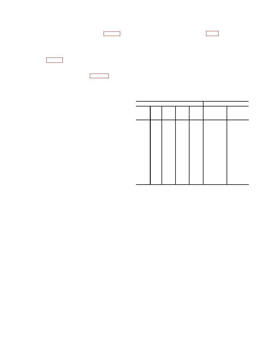
Table IV. Direct Current Check
Resistance decade is a load for unit
Resistance decade
Unit under test
under test.
When selecting
CURRENT
Meter
resistance,
use
controls
with
X0.1
X1
X10
X100
X100
switch
(M1)
adequate current rating.
position
indication
10
0
0
0
0
1 Amp
10
0
2
0
0
0
500 MA
5
b. Adjustments.
0
4
0
0
0
250 MA
2.5
0
0
1
0
0
100 MA
10
(1) Turn unit under test CURRENT switch to
0
0
2
0
0
50 MA
5
100 MA.
0
0
4
0
0
25 MA
2.5
(2) On resistance decade, set X10 range
0
0
0
1
0
10 MA
10
switch to 1 and all others to 0.
0
0
0
2
0
5 MA
5
(3) Operate TEST switch and adjust unit
0
0
0
4
0
2.5 MA
2.5
under
test
DECREASE-INCREASE
0
0
0
0
1
1 MA
10
control for 1-volt indication on electronic
0
0
0
0
2
500
A
5
0
0
0
0
4
250
A
2.5
0
0
0
0
10
100 A
10
8


