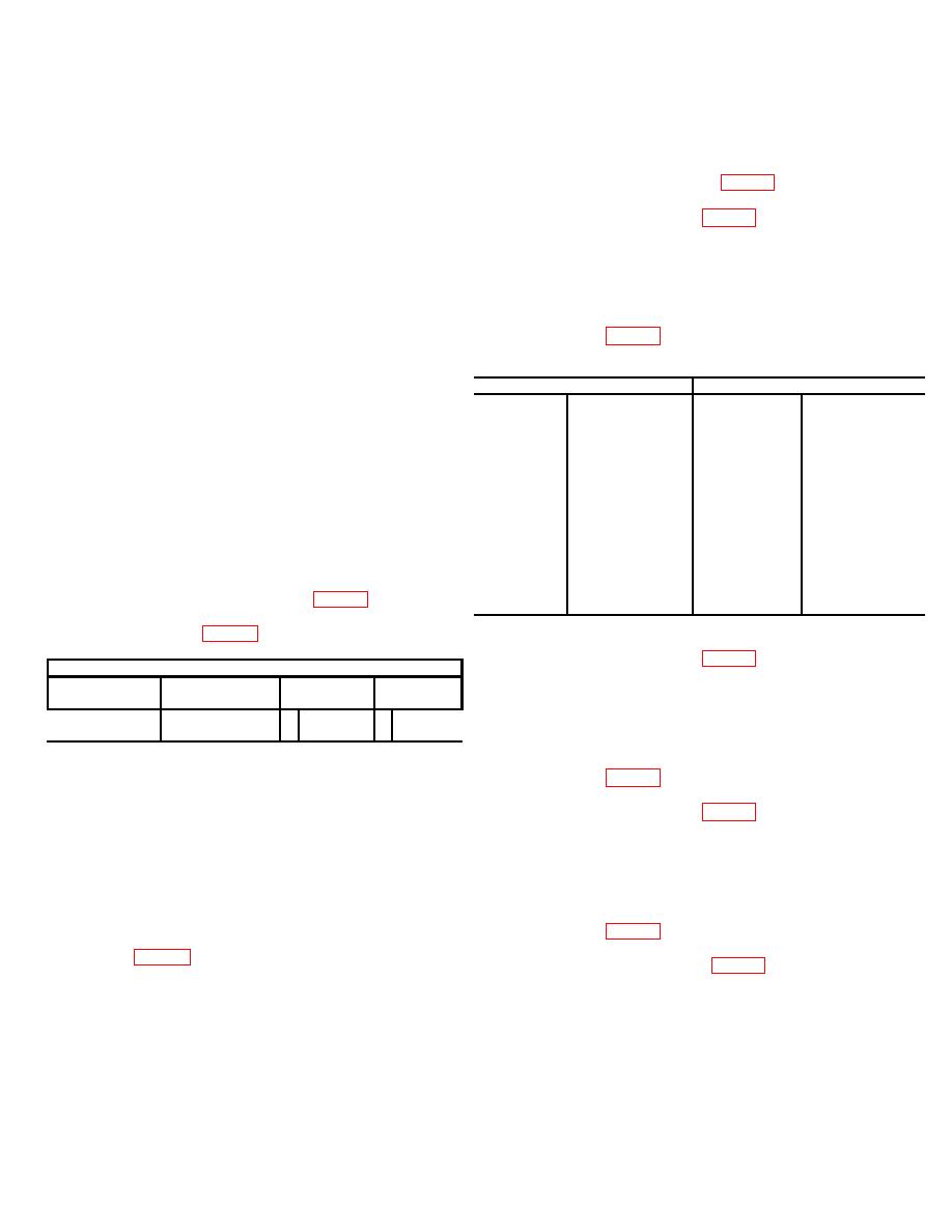
(1) Connect unit under test oscillator panel (1A1)
OUTPUT 1 connector to A INPUT of the frequency counter
b. Operate RF oscillator (lA1) FREQUENCY IN MHz
using RF cable assembly W118.
1, 2, 3, and 4 switches to OFF.
(2) Insure that MAINS switch is set to ON and
c. Disregard settings of. remaining controls and
that service strip power switch is set to on position.
switches on unit under test.
(3) Set oscillator panel (1A1) FREQUENCY IN
d. Operate service strip power switch to on position.
MHz 1 switch to positions noted in table 3.
Observe that service strip power indicator light illuminates.
External test equipment used during the calibration
(4) Observe that frequency counter indications
procedure can be connected to the service outlets for
are within the limits specified in table 3.
primary power.
(5) Return FREQUENCY IN MHz 1 switch to
OFF.
NOTE
(6) Remove RF cable assembly W118 from
The following paragraphs are divided
OUTPUT 1 connector and connect it to OUTPUT 2
into subparagraph a, performance
connector.
check,
and
subparagraph
b,
(7) Set FREQUENCY IN MHz 2 switch to
adjustments. When the performance
positions noted in table 4.
check is within tolerance do not
perform the corresponding adjustment.
Table 3. Oscillator Panel 1A1 OUTPUT 1 Frequencies
When the performance check is not
Unit under test
Frequency counter indication (Hz)
within
tolerance,
perform
the
FREQUENCY
corresponding
adjustment
before
IN MHz 1
continuing
with
the
calibration
Oscillator
switch position Minimum
Maximum
procedure.
When the performance
A22
2.300
22,999,885
23,000,115
check is not within tolerance and the
A23
26.750
26,749,866
26,750,134
adjustment cannot bring it into
A24
27.250
27,249,864
27,250,136
tolerance, the deficiency must be
A25
27.750
27,749,861
27,750,139
corrected before continuing with the
A26
147.000
146,997,060 147,002,940
procedure.
A27
151.750
151,746,965 151,753,035
A28
80.875
80,873,382
80,876,618
7. Power Supplies 1A3PS1 and 1A3PS2 Calibration
A29
86.000
85,998,280
86,001,720
a. Performance Check.
A30
86.625
86,623,267
86,626,733
(1) Connect dc voltmeter to test points on
A31
87.125
87,123,257
87,126,743
power supply panel (1A3) as noted in table 2.
A32
87.375
87,373,252
87,376,748
(2) Observe that dc voltmeter indicates within
the limits specified in table 2.
(8) Observe that frequency counter indications
Table 2. Power Supply Output Voltages
are within the limits specified in table 4.
Unit under test
Dc voltmeter indication
(9) Return FREQUENCY IN MHZ 2 switch to
Front panel
OFF.
Power supply
test points
Minimum
Maximum
(10) Remove RF cable assembly W118 from
1A3PS1
GND and 18
+17
+19
OUTPUT 2 connector and connect it to OUTPUT 3
A3PS2
GND and - 9
-8
-10
connector.
(11) Set FREQUENCY IN MHZ 3 switch to
b. Adjustments.
positions noted in table 5.
(1) Remove screws securing power supply
(12) Observe that frequency counter indications
panel (IA3) to cabinet frame.
are within the limits specified in table 5.
(2) Pull out panel until it docks into open
(13) Return FREQUENCY IN MHZ 3 switch to
position.
OFF.
(3) Remove popover supply panel (1A3) cover
(14) Remove RF cable assembly W118 from
screen.
OUTPUT 3 connector and connect it to OUTPUT 4
(4) Locate voltage adjust potentiometers on
connector.
power supplies 1A3PS1 and 1A3PS2.
(15) Set FREQUENCY IN MHZ 4 switch to
(5) Rotate the voltage adjust associated with
positions noted in table 6.
each power supply to obtain indications with the limits
(16) Observe that frequency counter indications
specified in table 2.
are lecithin the limits specified in table 6.
(6) Disconnect dc voltmeter from power supply
(17) Return FREQUENCY IN MHZ switch to OFF.
panel 1A3 test points.
(18) Remove RF cable assembly W118 from
(7) Replace
cover
screen
on
power
subassembly!'
(8) Secure power supply panel (1A3) to cabinet
frame with holding screws.
8. Oscillators 1A1A1 Through 1A1A43 Calibration
a. Performance Check.
4


