(3) Set TI CALIBRATE switch to 2 MHz. If
(2) Connect digital voltmeter to TI A4TP1. If
electronic counter does not indicate between 1,9999
digital voltmeter does not indicate between -14.98 and
and 2.0001 MHz, perform b below.
-16.02 V dc, perform b(2) below.
(3) Connect digital voltmeter to TI A4TP3, Digital
(4) Install TI top cover.
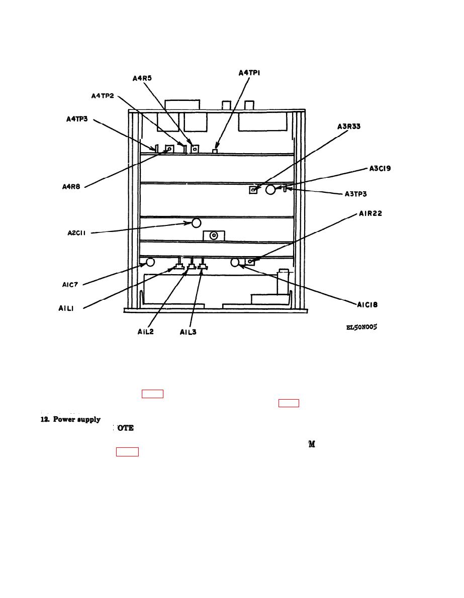
b. Adjustments Adjust A3C19 (fig. 5) to obtain an
voltmeter will indicate between 4.7 and 5.3 V dc.
b. Adjustments (fig. 5)
indication on electronic counter between 1.9999 and
2.0001 MHz.
(1) Adjust A4R5 for an in-tolerance indication.
(2) Adjust A4R8 for an in-tolerance indication.
N
13. Final Procedure. a. Deenergize and disconnect
Do not perform power supply check if all other
all equipment and install TI protective cover.
b. In accordance with T 38-750, annotate and
parameters are within tolerance.
a Performance Check (Fig. 5)
affix DA Label 80 (US Army Calibration System).
(1) Remove TI top cover and connect digital
When the TI cannot be adjusted within tolerance, an-
voltmeter (A2) to TI A4TP2. If digital voltmeter does
notate and affix DA Form 2417 (Unserviceable or
not indicate between 14.98 and 15.02 V dc, perform
Limited Use) tag.
b(1) below.


