
TB 9-4931-383-50
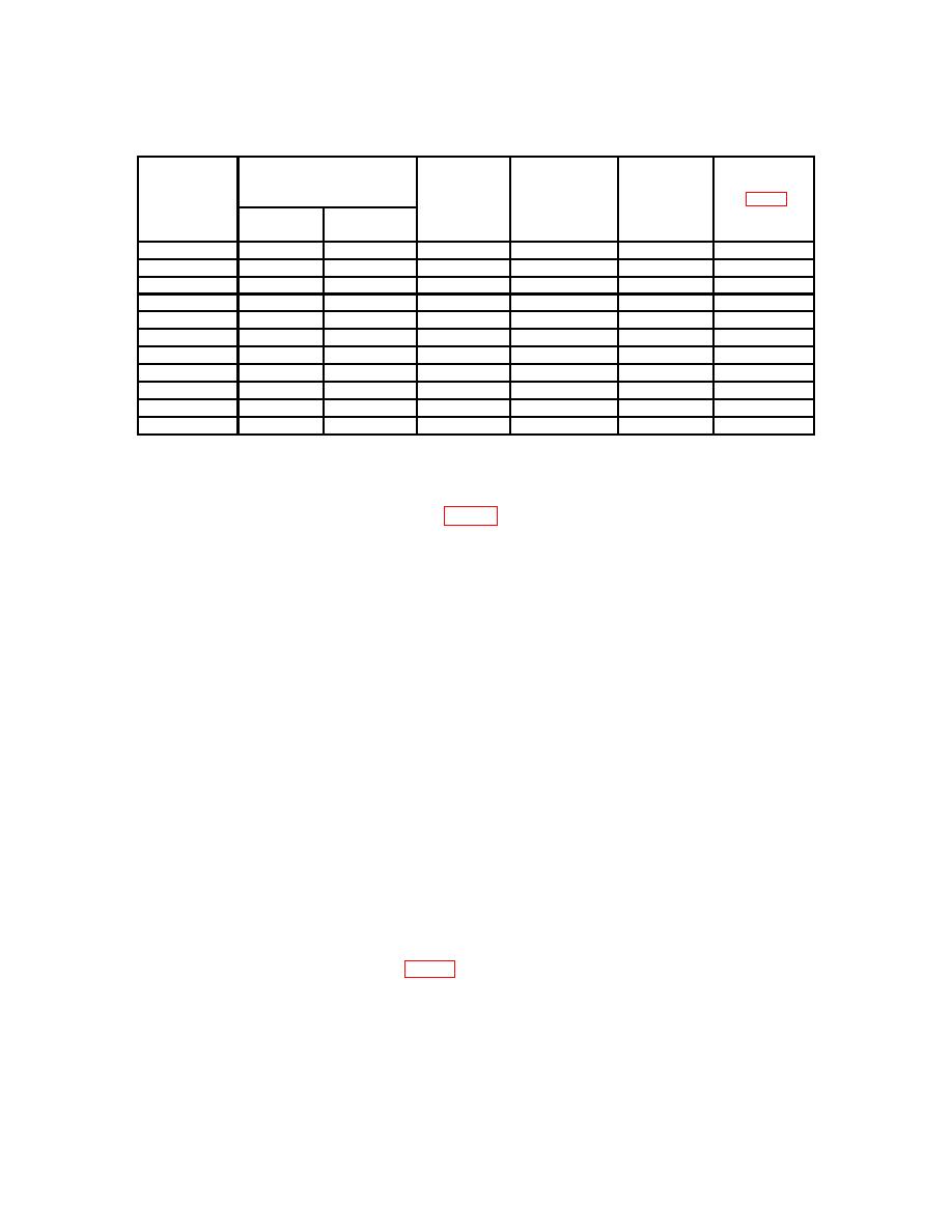
Table 6. Linearity
Maximum
Dc Transfer
Voltage
VOLTAGE
Test Instrument
Difference
Adjustment
Standard
Divider
RANGE
Switch Settings.
Allowed
s (fig. 5)2
Output.
Initial
Voltage Dial
Step
Step (5)
Setting
(V)1
(3)(B)
1000
01X.0000
020.0000
.5000000
10-volt mean
10
B2 (R)
1000
03X.0000
040.0000
.2500000
10-volt mean
10
B4 (R)
1000
05X.0000
060.0000
.1666666
10-volt mean
20
B6 (R)
1000
07X.0000
080.0000
.1250000
10-volt mean
20
B8 (R)
1000
09X.0000
0X0.0000
.1000000
10-volt mean
20
BX (R)
100
0X.00000
10.00000
.1000000
1-volt mean
1
A1 (R)3
100
1X.00000
20.00000
.5000000
10-volt mean
10
A2 (R)
100
3X.00000
40.00000
.2500000
10-volt mean
10
A4 (R)
100
5X.00000
60.00000
.1666666
10-volt mean
20
A6 (R)
100
7X.00000
80.00000
.1250000
10-volt mean
20
A8 (R)
100
9X.00000
100.00000
.1000000
10-volt mean
20
A10 (R)
1If
difference exceeds this value, perform adjustment.
2Report
adjustments only if difference is greater than 100 microvolts.
3Report this adjustment if difference is greater than 30 microvolts.
(1) Adjust DECK B adjustment 1 (fig. 5) for same indication on null detector (R).
(Report only if difference is greater than 30 microvolts.)
(2) Repeat a above until no further adjustments required.
18. Linearity (Model 332B/AF)
a. Performance Check
(1) Set voltage divider (A7) to .999999X.
(2) Set dc transfer standard (A2) for a 1-volt mean output.
(3) Position TI controls as listed in (a) through (c) below:
(a) VOLTAGE RANGE switch to 1000.
(b) Voltage dials to 000.X000.
(c) POWER switch to OPR.
NOTE
If null indication cannot be obtained at a 000.X000 dial setting,
adjust R1, CAL 1000V (fig. 6) to obtain a null indication.
(4) Adjust voltage divider for a null indication on null detector (A4) (within 10
microvolts). Record null detector indication.
(5) Set voltage dials to 001.0000.
26
