
TB 9-4931-527-40
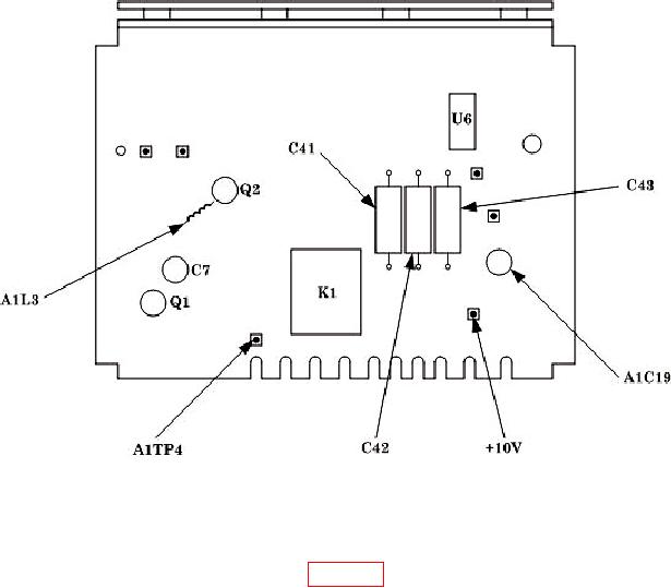
Figure 1. Calibration fixture - adjustment and test points.
9. FM Distortion
a. Performance Check
(1) Connect equipment as shown in figure 2.
(2) Set TI TEST MODE switch to FM.
(3) Set function generator controls for a 10 kHz, -18 dBm output.
(4) Set measuring receiver to measure frequency in track tune mode.
(5) Adjust TI CARRIER FREQUENCY TUNE until measuring receiver indicates
400.000 0.010 MHz.
(6) Set measuring receiver controls to measure average FM with a 50 Hz high pass
filter (low pass filters and FM de-emphasis off).
(7) Adjust function generator amplitude for a 20 kHz indication on measuring receiver.
NOTE
Perform (8) through (11) below quickly to minimize effects of TI
carrier drift on measurement.