
TB 9-4931-532-40
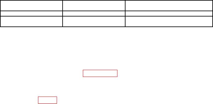
Table 2. Minimum Specifications of Equipment Required
Manufacturer and model
Common name
Minimum use specifications
(part number)
SURFACE PLATE
Accuracy:
Grade A
36"X48" (GGG-P-463)
THEODOLITE1
Range: 0 to 6400 mils
Wild, T2
0.05 mil
(MIL-T-14132)
Accuracy:
Limited deployment physical set, p/o LANCE calibration kit.
1
CALIBRATION PROCESS
6. Preliminary Instructions
a. The instructions outlined in paragraphs 6 and 7 are preparatory to the calibration
process. Personnel should become familiar with the entire bulletin before beginning the
calibration.
b. Items of equipment used in this procedure are referenced within the text by common
name as listed in table 2.
c. Unless otherwise specified, verify the result of each test and,
whenever the test requirement is not met, take corrective action before
continuing with the calibration.
d. Unless otherwise specified, all controls and control settings refer to
the TI.
7. Equipment Setup
WARNING
HIGH VOLTAGE is used or exposed during the performance of
this calibration.
DEATH ON CONTACT may result if
personnel fail to observe safety precautions.
REDUCE
OUTPUT(S) to minimum after each step within the
performance check where applicable.
a. Place TI on surface plate.
b. Place collimator projector on azimuth test fixture.
c. Connect collimator projector to a 115 V ac source and set switch to ON.
d. Mount azimuth test fixture adapter on azimuth test fixture support plate and secure
with cam locks.
e. Place theodolite on azimuth test fixture adapter.
f. Level theodolite through 6400 mils of azimuth dial.
g. Rotate azimuth test fixture dial to 0 and lock.
h. Place telescope in line-of-sight to collimator projector.