
TB 9-4935-367-24
(b) Release REL/dBm pushbutton (out).
(c) Set dBm REFERENCE
switch to 600.
(d) Press dB/VOLTS pushbutton (in).
(e) Press REL pushbutton (in).
(f) The display should indicate 0 dB and RELATIVE REFERENCE light should be lit.
(5) Set OUTPUT ATTENUATOR switch to +10 dBm.
(6) True rms voltmeter will indicate between -9.5 to -10.5 dBm.
(7) Repeat technique of (5) and (6) above using settings listed in table 7. True rms
voltmeter will indicate within limits specified.
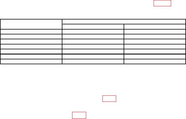
Table 7. Output Attenuation Accuracy
OUTPUT ATTENUATOR
True rms voltmeter indications (dB)
switch settings (dBm)
Min
Max
0
-19.5
-20.5
-10
-29.5
-30.5
-20
-39.5
-40.5
-30
-49.5
-50.5
-40
-59.5
-60.5
-50
-69.5
-70.5
-60
-79.5
-80.5
b. Adjustments. No adjustments can be made.
13. Power Supply
a. Performance Check
(1) Connect multimeter between A1 PIN 7 (fig. 1) and signal ground.
(2) If multimeter does not indicate between -35.5 V dc and -36.5 V dc, perform b below.
a. Adjustments. Adjust A1R3 (fig. 1) for a -36.0 V dc indication on multimeter (R).
14. Final Procedure
a. Deenergize and disconnect all equipment.
b. Annotate and affix DA label/form in accordance with TB 750-25.