
TB 9-5210-204-24
(3) Adjust micrometer ratchet as necessary to obtain a measurement of the ball
diameter. Note indication to the nearest 0.0001 inch.
NOTE
If TI has a 0.001 inch readout micrometer, read to the nearest
one-half minor division. If TI has a 0.0001 inch vernier, read
direct.
(4) Repeat technique of (2) and (3) above for points B, C, D and E.
ball micrometer tester small ball with large ball (0.250 in.) and repeat technique of (2) through
(4) above.
(6) For 0.001 inch readout micrometers, verify that the five readings have a
maximum difference of one-half of a minor division for each ball. Use tolerances in table 4
for 0.0001 inch readout micrometers. If readings are within tolerance, proceed to
Table 4. Parallelism Tolerance for Outside Micrometer Calipers
Test instrument
Size
Range
Tolerance
Inches
Millimeters
Inches
Millimeters
Inches
Millimeters
1
25
0 to 1
0 to 25
0.00010
0.0025
2
50
1 to 2
25 to 50
0.00010
0.0025
3
75
2 to 3
50 to 75
0.00020
0.0050
4
100
3 to 4
75 to 100
0.00020
0.0050
5
125
4 to 5
100 to 125
0.00020
0.0050
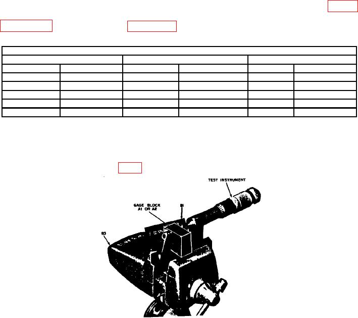
(7) If TI basic length is 1 to 5 inches, perform technique of (8) through (15) below:
(8) Place vise on a flat level surface.
(9) Place TI in vise so TI is at a 90 degree angle from work surface and spindle is
parallel to rubber jaws of vise (fig. 2).
Figure 2. Parallelism Test - Equipment Setup.
5