
TB 9-6625-1200-24
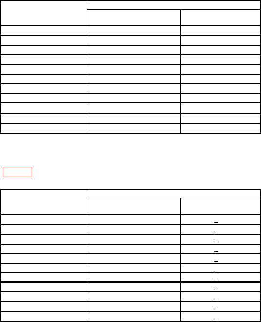
Table 3. Channel 1 Vertical Deflection
Oscilloscope calibrator
CH1 VOLTS/DIV
VOLTAGE
Err display
settings
settings
(%)
0.1
0.4
V
3.0
0.01
40
mV
3.0
0.02
80
mV
3.0
0.05
200
mV
3.0
0.2
0.8
V
3.0
0.5
2.0
V
3.0
1
4
V
3.0
2
8
V
3.0
5
20
V
3.0
10
40
V
3.0
20
80
V
3.0
(5) Set oscilloscope calibrator to standby and select oscilloscope calibrator CHAN 2.
(6) Set CH1-CH2 mode switch to CH2 and repeat technique of (2), (3), and (4)
above, using table 4. If not in tolerance in (4) above, perform b (1) and (3) below.
Table 4. Channel 2 Vertical Deflection
Oscilloscope calibrator
CH1 VOLTS/DIV
VOLTAGE
Err display
settings
settings
(%)
0.1
0.4
V
+3.0
0.01
40
mV
+3.0
0.02
80
mV
+3.0
0.05
200
mV
+3.0
0.2
0.8
V
+3.0
0.5
2.0
V
+3.0
1
4
V
+3.0
2
8
V
+3.0
5
20
V
+3.0
10
40
V
+3.0
20
80
V
+3.0
(7)
Set oscilloscope calibrator to standby.
Set CH 2 VOLTS/DIV switch to .05.
(8)
Set oscilloscope calibrator for a VOLTAGE output of 20 mV and frequency of 1 kHz.
(9)
(10) Pullout X10 GAIN AC switch.
(11) Adjust oscilloscope calibrator knob located below the EDIT FIELD key for 4
divisions displayed on TI crt. Err displayed on oscilloscope calibrator will be within 4.0
percent ( 7.5 percent for S/N below 20,000).
(12) Push in X10 GAIN AC switch.
(13) Set oscilloscope calibrator to standby.
5