TB 9-6625-194-24
ADJUSTMENTS
Model i400s
(1) Set the Ammeter Calibrator to the 20 A range and the Calibrator output for
0.66 V ac @ 45 Hz.
(2) Set the Calibrator OPR/STBY switch to OPR. Press the Ammeter Calibrator
OPERATE pushbutton.
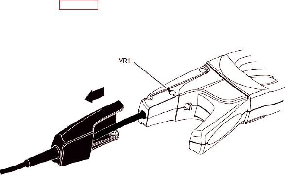
(3) Referring to figure C-1, slide the rubber boot on the TI handle back to access the
adjustment point, VR1.
(4) Using a small flat-head screwdriver, adjust VR1 for a meter reading of 98.9 mV
to 99.1 mV.
Figure C-1. Model i400s Adjustment Location.
Model 80i-500s
(1) Connect Calibrator OUTPUT to the Ammeter Calibrator INPUT terminals,
observing polarity.
(2) Connect the 15-turn coil to the Ammeter Calibrator.
(3) Connect the Multimeter INPUT to TI output terminals.
(4) Set the Calibrator for 0.266 V ac @ 50 Hz. Set the Ammeter Calibrator Range to
100 A. This produces 399 ampere-turns in the center conductor bundle of the coil.
(5) Set the Calibrator OPR/STBY switch to OPR and press Ammeter Calibrator
OPERATE pushbutton.
(6) Clamp the Current Probe around the coil. (The probe jaws must be centered
around the coil.)
(7) Adjust the calibration potentiometer (accessible next to cable input to probe
handle) to read 402 mV ac on the DMM.
(8) Verify calibration by rechecking the test points.
C-1/(C-2 blank)

