
TB 9-6625-1947-24
b. Adjustments
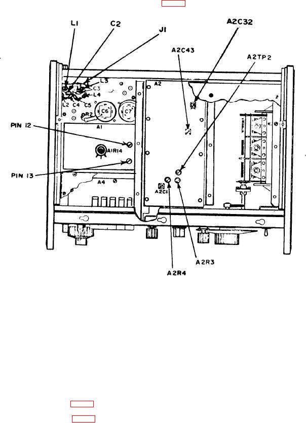
(1) Connect multimeter between A2TP2 (fig. 1) and chassis ground termination.
-R15-
Figure 1. Adjustment locations - bottom view.
f
(2) Connect audio analyzer or spectrum analyzer to TI UNBAL output, using 50
eed-through termination.
(3) Position controls as listed in (a) through (d) below:
(a) FREQUENCY RANGE switch to X1K.
(b) FREQUENCY dial fully cw.
(c) OUTPUT LEVEL dBm switch to +10.
(d) AMPLITUDE control fully ccw.
(4) Adjust A2R3 (fig. 1) for a -350 mV indication on multimeter (R).
(5) Adjust A2R4 (fig. 1) for minimum distortion on audio analyzer, or at least -46 dB
on the spectrum analyzer (R).
(6) Rotate FREQUENCY dial fully ccw.
6