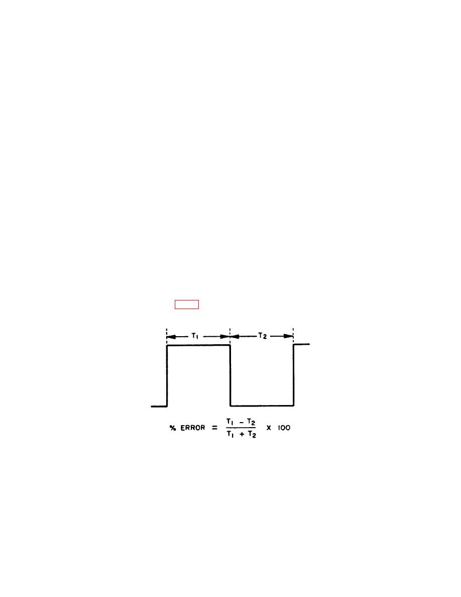
TB 9-6625-1966-35
8. Symmetry
a. Performance Check
(1) Position controls as listed in (a) through (d) below:
(a)
RANGE switch to X.1.
(b)
CHANNEL A function switch to SQUARE.
(c)
CHANNEL AMPLITUDE control to midrange.
(d)
FREQUENCY dial to 10.
(2) Connect calibrator to FREQUENCY CONTROL (rear panel).
CAUTION
Voltage must be limited to between +0.3 and -15 V. Voltage
outside this range will damage TI. Do not use standby/reset
position of calibrator.
(3) Adjust calibrator output to 0.3 V.
(4) Connect frequency counter to TI CHANNEL A OUTPUT.
NOTE
For convenience (because of long time interval of TI signal),
obtain initial settings for start and stop channels with TI
RANGE switch turned to X100; then, set RANGE switch to
X.1 and continue with performance check.
below.
7


