
TB 9-6625-1976-24
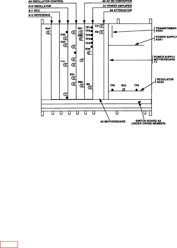
Figure 1. Ac calibrator - adjustment locations.
9. Distortion
a. Performance Check
(1) Connect TI OUTPUT to audio analyzer HIGH and LOW INPUT terminals
using a balanced cable.
(2) Press audio analyzer FLOAT key (assure illumination).
(3) Set FREQUENCY RANGE-Hz switch to 100 kHz and FREQUENCY dials to
50.00 K.
(4) Set VOLTAGE RANGE switch to 100 V and VOLTAGE dials to 10.0000 V.
(5) Set SENSE switch to INT and MODE switch to OPER.
(6) Measure distortion. If distortion is not less than 0.041 percent, perform b below.
(7) Adjust resistance standard to 200
and connect across TI output.
(8) Measure distortion. If distortion is not less than 0.07 percent, perform b below.
(9) Repeat technique of (1) through (8) above for settings and indications listed in