
TB 9-6625-2004-35
(2) Connect synthesized signal generator to TI input.
(3) Set synthesized signal generator frequency to 20 MHz and level to 5 mV.
(4) Fine tune synthesized signal generator frequency for a 0 indication on CARRIER
SHIFT meter and a black line indication on LIMITING meter. Synthesized signal
generator final indication will be between 18.00 and 22.00 MHz.
NOTE
If TI interference is encountered during this check,
momentarily disconnect TI, verify generated frequency on
frequency counter, and reconnect TI.
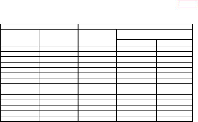
(5) Repeat technique of (3) and (4) above, using settings listed in table 4.
If
synthesized signal generator does not indicate within limits specified, perform b below.
Table 4. RF Oscillator
Test instrument
Synthesized signal generator
FREQUENCY
FREQUENCY-
Final indications
RANGE-MC
MC
Initial settings
(MHz)
switch settings
dial settings
(MHz)
Min
Max
20-55
35
35
31.5
38.5
20-55
50
50
45
55
55-120
60
60
54
66
55-120
87.5
87.5
78.75
96.25
55-120
115
115
103.5
126.5
120-250
130
130
117
143
120-250
185
185
166.5
203.5
120-250
240
240
216
264
250-500
260
260
234
286
250-500
375
375
337.5
412.5
250-500
475
475
427.5
522.5
500-1000
550
550
495
605
500-1000
750
750
675
825
500-1000
900
900
810
990
b. Adjustments
(1) Set FREQUENCY RANGE-MC switch to 20-55.
(2) Set synthesized signal generator frequency to 35 MHz.
(3) Loosen setscrew that holds FREQUENCY-MC dial to oscillator shaft and adjust
oscillator shaft for a 0 indication on CARRIER SHIFT meter.
(4) Adjust FREQUENCY-MC dial to 35 MHz and tighten setscrew.
(5) Repeat a above.
5