
TB 9-6625-2023-35
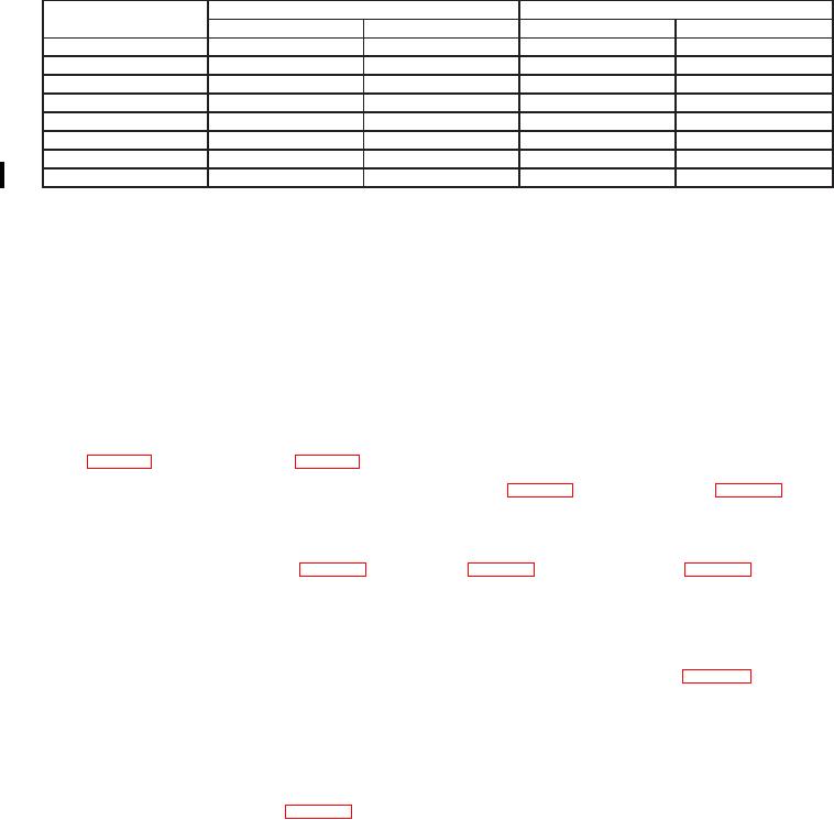
Table 6. Ac Voltage - Continued
Test instrument
Calibrator output settings
Test instrument indications
RANGE settings
Voltage (V)
Min
Max
10
10
400
kHz
9.43
10.57
10
10
1
MHz
9.02
10.98
100
100
30
Hz
99.88
100.12
100
100
100
Hz
99.88
100.12
100
100
40
kHz
99.27
100.73
100
100
100
kHz
99.27
100.73
1000
1000
40
Hz
997
1003
1000
1000
10
kHz
997
1003
b. Adjustments
NOTE
Adjustments are labeled on top inner cover. Top inner cover
must be removed to gain access to test points on circuit boards.
(1) Set calibrator to STANDBY and disconnect from TI.
(2) Press TI RANGE 10 key to on.
(3) Short INPUT (2 WIRE) HI and LO using copper wire or shorting bar.
(4) Connect multimeter (V dc mode) INPUT HI to A15 TP8 (fig.1) and LO to A15
multimeter indicates 0 V dc r10 PV (R).
(6) Disconnect multimeter.
indicates 0 V r1 count (R).
(8) Disconnect A15 TP3 from A15 TP6 and short from INPUT (2 WIRE) HI and LO.
(9) Connect calibrator OUTPUT HI and LO to TI INPUT (2 WIRE) HI and LO.
(10) Set calibrator for a 100 mV, 100 Hz output. Adjust A15 R29 (fig. 1) until TI
indicates between 0.0998 and 0.1002 V (R).
(11) Set TI rear panel AC-AC/DC switch to AC/DC.
(12) Set calibrator for a 10 V dc output. Record TI indication.
(13) Set calibrator for a +10 V dc output. Record TI indication.
(14) Adjust A15 R51 (fig. 1) so that indications recorded in (12) and (13) above are
equal r0.0005 V (R).
(15) Repeat (12) through (14) above as necessary.
(16) Set calibrator to STANDBY.
(17) Set TI rear panel AC-AC/DC switch to AC.
(18) Press TI RANGE 1 key to on.