
TB 9-6625-2049-24
(15) Set frequency counter controls to measure frequency. If frequency counter does
not indicate between 59.99970 and 60.00030 MHz, perform b below.
b. Adjustments
(1) Disconnect TI rear panel 10 MHz OVEN OUTPUT from EXT REF IN option
001 only.
(2) Connect frequency counter CHANNEL A to TI rear panel AUX 21-60 MHz.
(3) Press keys and enter values using DATA keys as listed in (a) through (c) below:
(a) FUNCTION sine wave.
(b) ENTRY FREQ.
(c) 60 MHz.
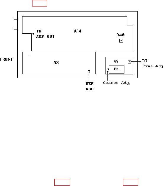
(4) Adjust REF R30 (fig. 3) until frequency counter indicates 60.000000 MHz (R).
Figure 3. Test instrument - bottom view.
(5) Disconnect frequency counter from TI rear panel AUX 21-60 MHz.
(6) Connect frequency counter CHANNEL A to TI SIGNAL.
(7) Enter 20 MHz using DATA keys.
Frequency counter will indicate between
19.99990 and 20.00010 MHz.
(8) Disconnect frequency counter from TI.
(9) Perform (10) through (14) below for option 001 only.
(10) Program time/frequency workstation for a 1 MHz output and connect to
frequency difference meter REF INPUT.
(11) Connect TI rear panel 10 MHz OVEN OUTPUT to frequency difference meter
SIG INPUT.
indication on frequency difference meter.
12