
TB 9-6625-2071-24
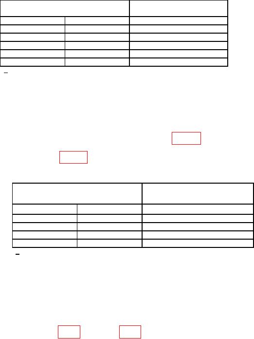
Table 4. Channel A Sensitivity AC.
Adjusted function generator
Function generator output
output
(kHz)
(mVp-p)
(mVp-p)
≤ 711
0.02
1.0
≤ 711
1.00
1.0
≤ 711
10.00
1.0
≤ 711
100.00
1.0
≤ 711
1000.00
1.0
<42 mVp-p for AN/USM-459 and 5328AF096.
1
(5) Disconnect function generator from TI.
(6) Connect signal generator RF OUTPUT to TI INPUT A using 50 Ω feedthrough
termination (omit termination for option H60).
(7) Set TI FREQ RESOLUTION, N switch to 10Hz, 105.
(8) Set signal generator for each output listed in table 5, and slowly increase signal
generator amplitude until TI indication is stable. If adjusted signal generator amplitude
exceeds limits specified in table 5, perform b (1) through (4) below (b (5) through (10) below
for AN/USM-459 and 5328AF096).
Table 5 Channel A Sensitivity.
Adjusted signal generator
Signal generator output
amplitude
(MHz)
(mV)
(mV)
≤ 251
10
1.0
≤ 251
34
1.0
≤ 50
50
1.0
≤ 50
100
1.0
<15 mV for AN/USM-459 and 5328AF096.
1
(9) Set TI CHANNEL A DC/AC switch to DC and repeat (8) above.
b. Adjustments
(1) Connect signal generator RF OUTPUT to TI INPUT A using 50 Ω feedthrough
termination (omit termination for option H60).
(2) Set signal generator for a 40 MHz, 25 mV output.
approximately 40 MHz.
NOTE
Do not adjust sensitivity below 10 mV.
(4) Slowly decrease signal generator output and repeat (3) above.
(5) Connect TI CHANNEL A MARKER OUTPUT to oscilloscope Vertical 1 input
using a 50 Ω feedthrough termination.
(6) Set oscilloscope channel 1 for DC input coupling, 1 MΩ input, 500mV/div
amplitude and 10 μs/div sweep.
7