
TB 9-6625-2077-35
b. Adjustments
(1) Set POWER switch to OFF.
(2) Remove cover from TI.
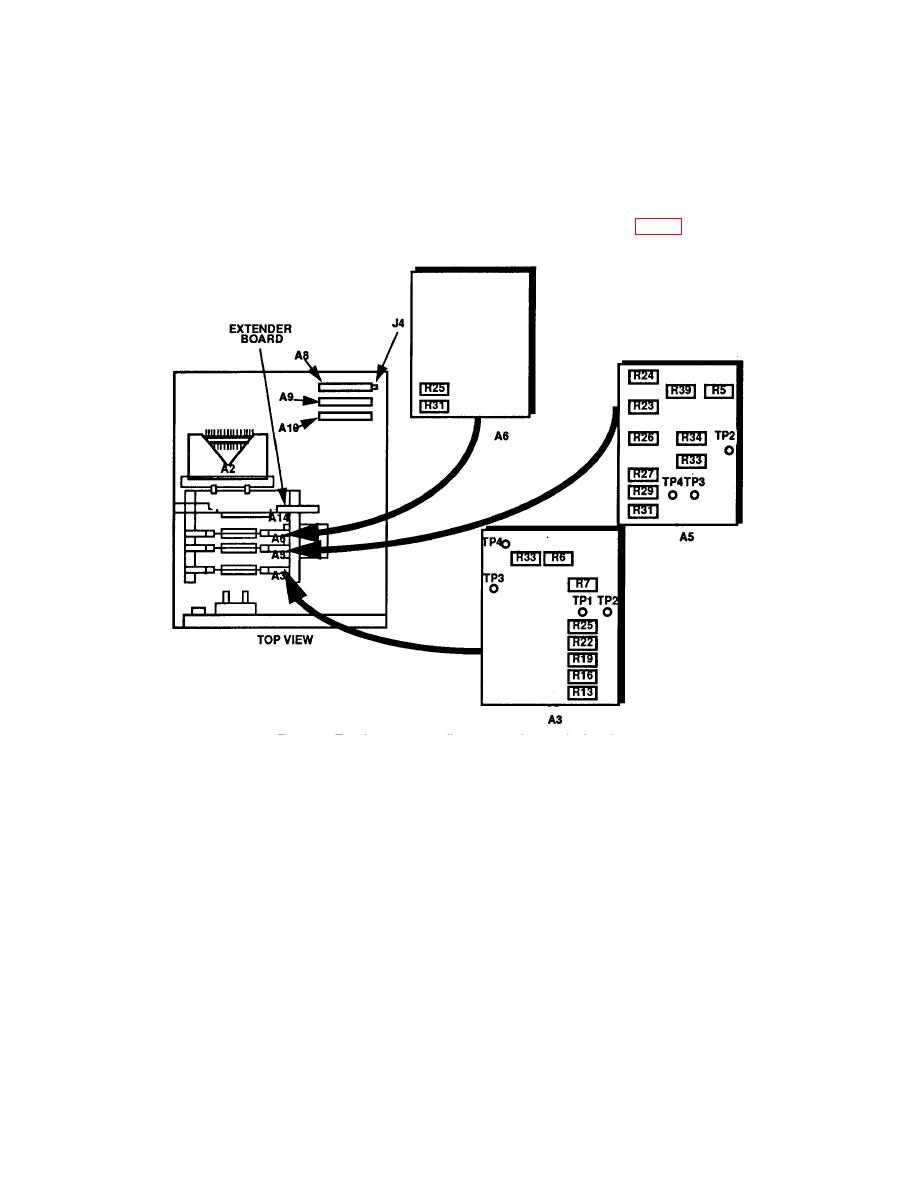
(3) Remove assembly A3 and reconnect using extender board (fig. 1).
(4) Position controls as listed in (a) through (e) below:
(a) POWER switch to ON.
(b) MODULATION switch to CW.
(c) RF OUTPUT switch to 0 dBm.
(d) TUNING RANGE switch to 16-90 MHz (16-80 MHz).
(e) RF OUTPUT LEVEL control for 0 dB indication on TI RF OUTPUT
meter.
(5) Connect TI RF OUTPUT to measuring receiver power sensor and adjust
TUNING COARSE and FINE control for an indication of 80.00000 MHz on measuring
receiver.
6
