
TB 9-6625-2084-24
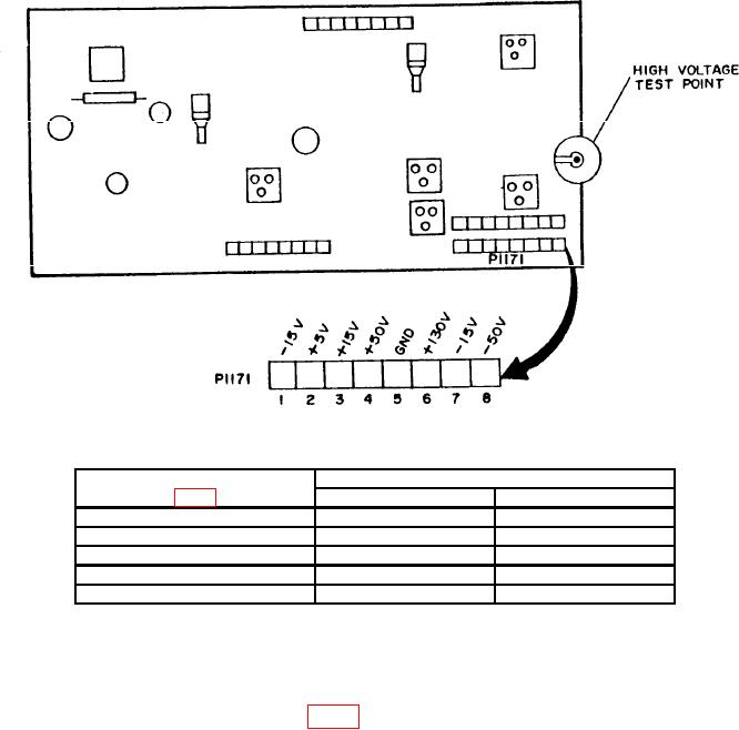
Figure 4. Board all power supply - top right rear view.
Table 4. Power Supply Check
Test instrument test points
Digital voltmeter indications (V dc)
Min
Max
-15
Pin 1
-14.9
-15.1
+5
Pin 2
+4.9
+5.1
+15
Pin 3
+14.9
+15.1
+50
Pin 4
+49.7
+50.3
+130
Pin 6
+125
+135
(5) Set POWER OFF/ON switch to ON. Digital voltmeter will indicate between -1430
and -1520 V dc.
(6) Set POWER OFF/ON switch to OFF and disconnect digital voltmeter.
b. Adjustments. Adjust -50 V R581 (fig. 3) for a -50-V indication on digital voltmeter (R).
15. Final Procedure
a. Deenergize and disconnect all equipment and reinstall protective cover on TI.
b. Annotate and affix DA label/form in accordance with TB 750-25.