
TB 9-6625-2102-35
(5) Set up frequency counter to measure period (50 Ω).
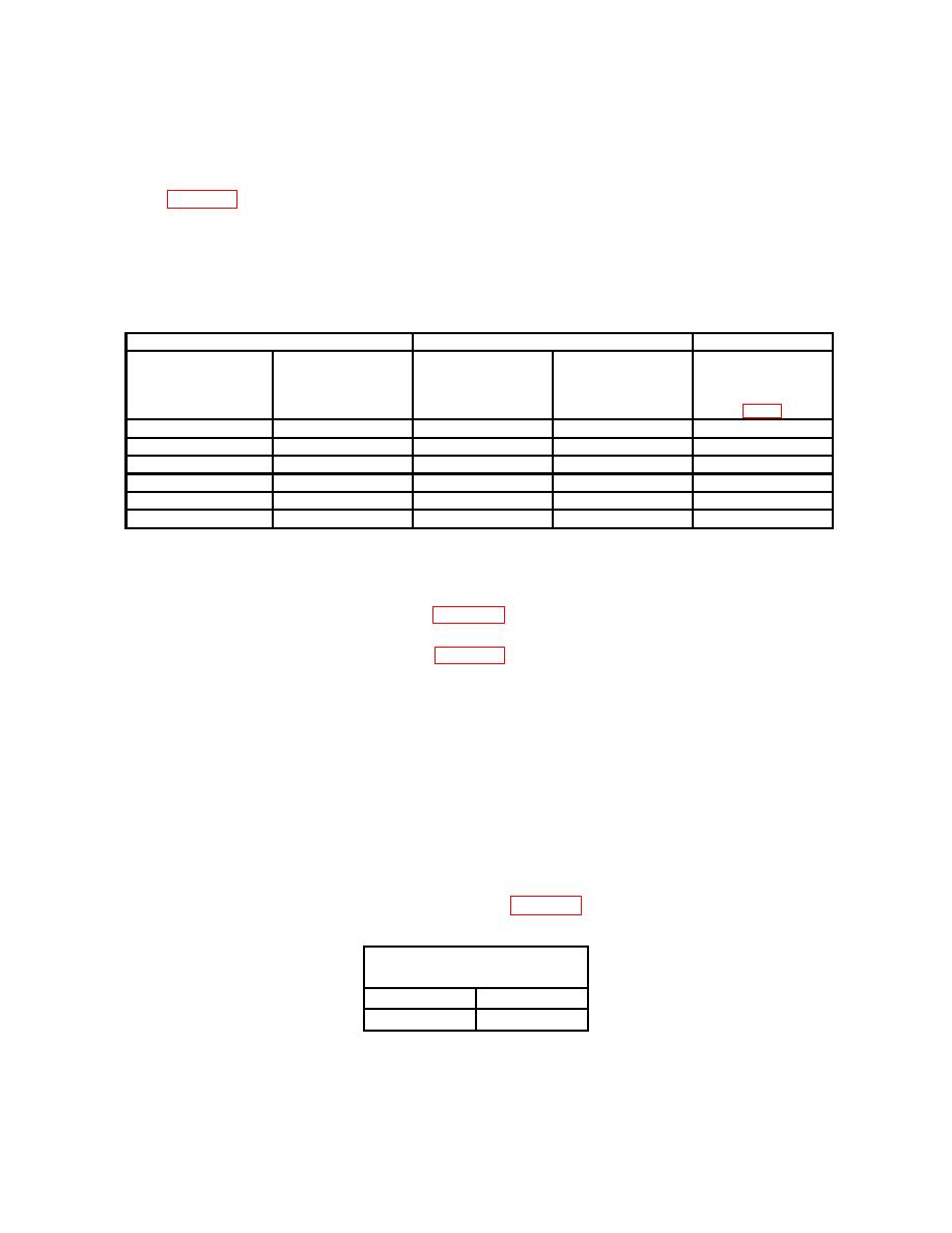
(6) Set TI FREQ/MULT(Hz) to switch settings and frequency dial position for each
row in table 19. If measured period using frequency counter does not indicate within limits,
perform b (2) below.
NOTE
The remaining tests are done using period measurements.
Some checks are lengthy.
Test instrument
Frequency counter indications (ms)
Test instrument
FREQ MULT (Hz)
switch
Adjustments
Frequency dial
settings
Max
Min
positions
10
2.0
48.07
52.08
R51 (R)
10
1.0
94.33
106.38
1
1.0
943.3
1063.8
1
2.0
480.7
520.8
.1
2.0
4807.0
5208.0
.01
2.0
48000.0
52000.0
(7) Disconnect frequency counter from TI.
b. Adjustments
(1) Perform adjustments listed in table 18 and repeat as required for in-tolerance
condition.
(2) Perform adjustments listed in table 19 and repeat as required for in-tolerance
condition
a. Performance Check
(1) Connect TI FUNCTION OUT (50 Ω) to audio analyzer INPUT HIGH using a
50 Ω feedthrough termination.
(2) Initiate audio analyzer and set to measure level with DC low-pass filter on.
(3) Set main FUNCTION switch to DC and adjust AMPLITUDE control fully ccw.
(4) If audio analyzer is not within limits in table 20, perform b (l) below.
Table 20. Zero
Audio analyzer indications
(V)
Min
Max
-.020
.020
(5) Disconnect TI from audio analyzer and 50 Ω feedthrough termination.
