
TB 9-6625-2112-35
(4) Adjust AMPLITUDE VERNIER control from minimum to maximum. If pulse
amplitude as indicated on oscilloscope does not vary from 50 V or less to 100 V or more,
perform b below.
(5) Set PULSE POLARITY switch to NEG and repeat technique in (4) above.
(6) Repeat technique in (3) through (5) above, using settings listed in table 5. Pulse
amplitude as indicated on oscilloscope will be within limits specified.
Table 5. Amplitude
Oscilloscope indications
Test instrument
(V peak)
Amplitude volts
Pulse polarity
Equal to or
Equal to or
switch settings
switch settings
less than
more than
501
+ and -
20
50
20
+ and -
10
20
10
+ and -
5
10
5
+ and -
2
5
2
+ and -
1
2
1
+ and -
0.5
1
0.5
+ and -
0.2
0.5
0.2
+ and -
0.08
0.2
1Remove
attenuator from input to 2465B-46.
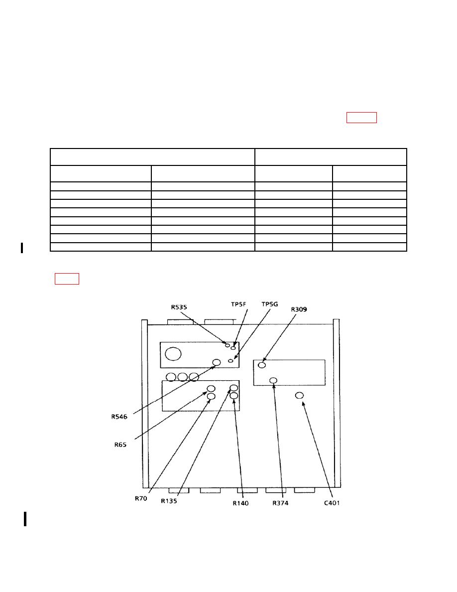
b. Adjustments. Adjust AMPLITUDE VERNIER control fully ccw and adjust R374
CHANGE 1
6
