
TB 9-6625-2119-24
d. When indications specified in paragraphs 8 through 11 are not within tolerance,
perform the battery zero check prior to making adjustments. After adjustments are made,
repeat paragraphs 8 through 11. Do not perform battery zero check if all other parameters
are within tolerance.
e. Unless otherwise specified, all controls and control settings refer to the TI.
7. Equipment Setup
HIGH VOLTAGE is used or exposed during the performance of
this calibration.
DEATH ON CONTACT may result if
personnel fail to observe safety precautions.
REDUCE
OUTPUT(S) to minimum after each step within the
performance check where applicable.
a. Position controls as listed in (1) through (4) below:
(1) POWER ON/OFF pushbutton pressed to ON.
(2) AC/DC mode pushbutton released to DC.
(3) V mode pushbutton pressed.
(4) Range 200 m pushbutton pressed.
b. Short TI V-
and COMMON inputs. Display will indicate 00.0 2 counts.
c. Remove short.
8. Dc Voltage
a. Performance Check
to calibrator OUTPUT HI and TI COMMON to calibrator
(1) Connect TI V-
OUTPUT LO.
(2) Set calibrator for an output amplitude of 190 mV dc. If TI does not indicate
within limits specified in first row of table 3, perform b below.
(3) Repeat technique of (2) above, using calibrator outputs and TI range settings
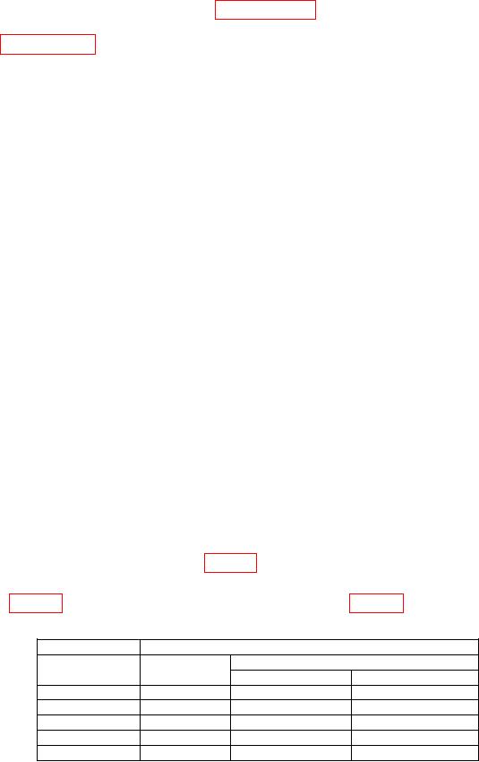
Table 3. Dc Voltage
Calibrator
Test instrument
Range
Indication limits (V dc)
Output
setting
Min
Max
190 mV
200 m
189.5
190.5
1.9 V
2
1.895
1.905
19 V
20
18.95
19.05
190 V
200
189.5
190.5
1000 V
1000
997
1003
(4) Set calibrator output to minimum.