
TB 9-6625-2143-24
(2) Connect rear panel OUTPUT to front panel INPUT.
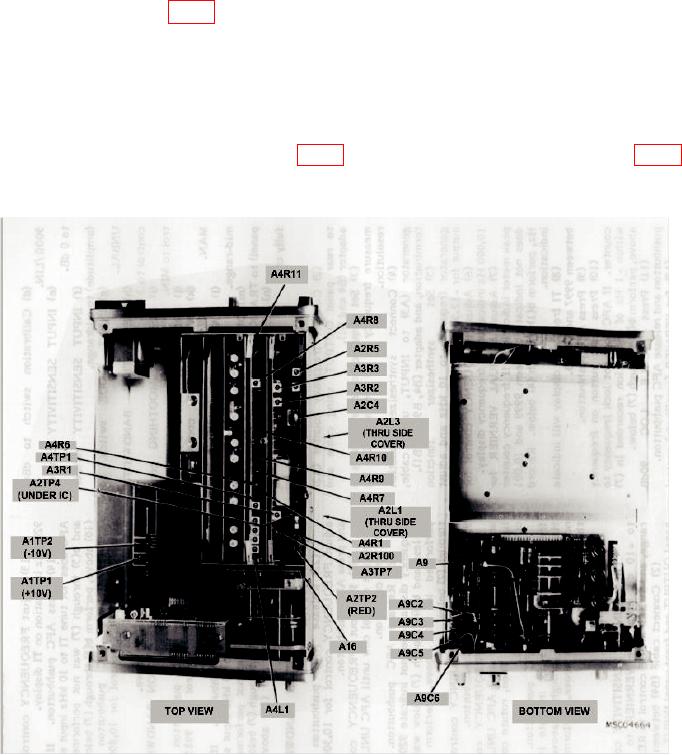
(3) Adjust A2C4 (fig. 1) for peak meter indication. (R)
(4) Disconnect cable connected in (2) above.
(5) Set INPUT SENSITIVITY and VERNIER controls to CAL, RESOLUTION
BANDWIDTH control to 10 Hz, and SWEEP MODE control to OFF.
(6) Adjust FREQUENCY control for exactly 10,000 Hz indication on TI display.
Press AFC pushbutton.
for multimeter indication of 0 0.5 V dc. (R)
Figure 1. Adjustments.
9. Frequency Span
a. Performance Check
(1) Position controls as listed in (a) through (n) below:
6