
TB 9-6625-2144-24
NOTE
The value of attenuation on output cable assembly CG-92A/U
(supplied with TI) is accurate to 0.3 dB at 8.5, 9.080, and 9.6
GHz and is stamped on a metal tag which is attached to each
unit. Since attenuation of this cable may change with time,
actual attenuation of this cable should be confirmed by the
following method to insure accurate calibration.
(6) Connect output cable assembly CG-92A/U between TI RF OUTPUT connector
and power meter.
(7) Repeat output power accuracy test and record new power indications.
(8) The difference between readings recorded in (4) and (5) above and readings
recorded (7) above will indicate actual cable attenuation loss 0.3 dB.
b. Adjustments. No adjustments can be made; however, a new correction chart may
be prepared and attached to TI if necessary.
11. Input Power Accuracy
a. Performance Check
(1) Set TRAN/TEST/RECV switch to TRAN and adjust SET ZERO COARSE and
FINE controls to obtain SET ZERO indication on SET POWER meter.
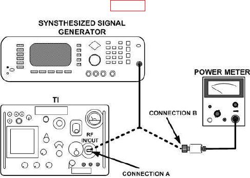
(2) Connect equipment as shown in figure 2, connection A.
Figure 2. Input - equipment setup.
(3) Adjust controls of synthesized signal generator for CW operation at 8.5 GHz
(15.8 GHz) and power level for an on-scale indication on SET POWER meter.