
TB 9-6625-2157-24
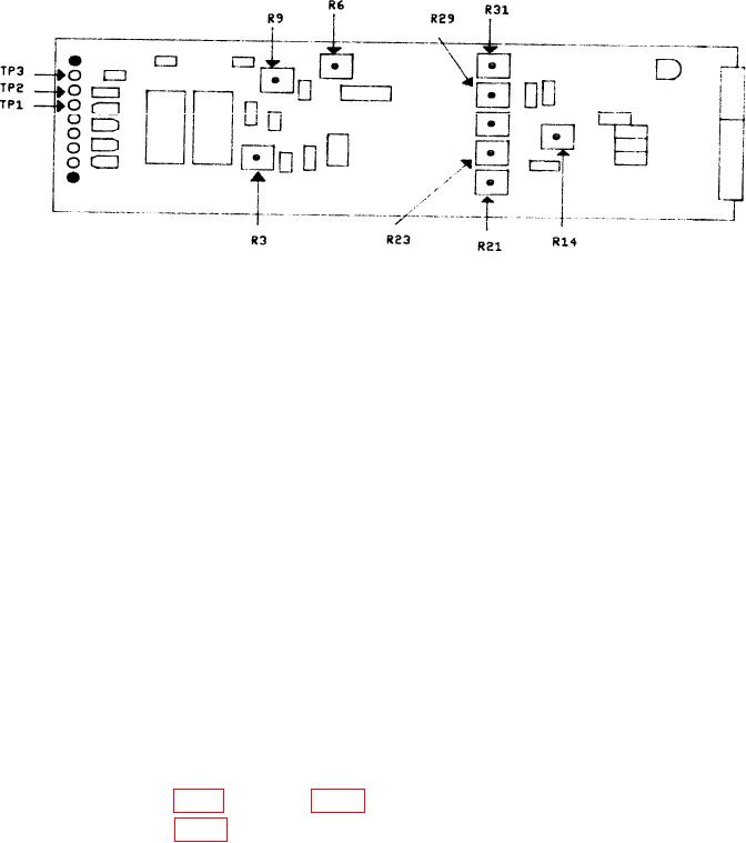
Note: Power supply assembly is located on bottom view of TI.
Figure 3. Power supply assembly - adjustment locations.
12. Rise and Fall Time
a. Performance Check
(1) Connect PULSE OR RF OUT connector to oscilloscope using coaxial crystal
detector and 50 termination.
(2) Set function switch to PULSED RF.
(3) Measure rise and fall times of pulse. If rise or fall times are not 10 ns or less,
perform b (1) below.
(4) If spikes are present, perform b (2) below.
(5) Remove coaxial crystal detector.
(6) Set function switch to + VIDEO PULSE.
(7) Measure rise and fall times. Rise and fall times will be 20 ns or less.
b. Adjustments
10 ns (R).
(2) Adjust R34 (fig. 1) for minimum spikes (R).
13. Meter
a. Performance Check
(1) Set function switch to CW.
(2) Set frequency control outer dial to 10-16 and inner dial to 10.