
TB 9-6625-2171-24
Figure 6. 9960 Hz FM deviation display with jitter expanded.
b. Adjustments. No adjustments can be made.
18. VOR Zero
a. Performance Check
(1) Connect zifor COMP INPUT to TI A6J9 (fig. 3).
If zifor does not indicate
between 359.3 and 000.7 degrees, perform b below.
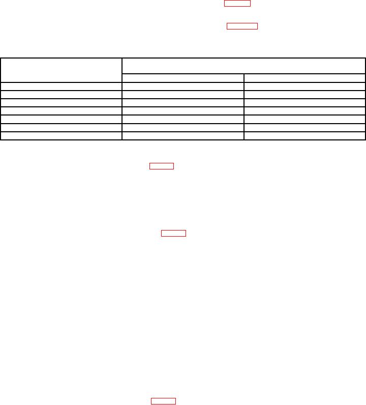
(2) Set VOR bearing switch to positions listed in table 5. Zifor will indicate within
limits specified.
Table 5. VOR Bearing
Test instrument
VOR bearing
Zifor indications
switch positions
Min
Max
045
044.0
046.0
090
089.0
091.0
135
134.0
136.0
180
179.0
181.0
225
224.0
226.0
270
269.0
271.0
315
314.0
316.0
b. Adjustments. Adjust A6R72 (fig. 3) for indication of 000.0 degrees on zifor (R).
19. LOC DDM
a. Performance Check
(1) Set VOR PWR switch to OFF and LOC PWR switch to ON. If VAR light is
illuminated, press light to extinguish.
(2) Connect multimeter to A6J2 (fig. 3).
(3) Press and hold LOC 150 Hz pushbutton. Record multimeter indication.
(4) Set LEFT-OC-RIGHT switch to LEFT. Record multimeter indication.
(5) Set LEFT-OC-RIGHT switch to RIGHT. Record multimeter indication.
(6) Release LOC 150 Hz pushbutton and press and hold LOC 90 Hz pushbutton.
Record multimeter indication.
(7) Set LEFT-OC-RIGHT switch to OC. Record multimeter indication.
(8) Set LEFT-OC-RIGHT switch to LEFT. Record multimeter indication.
(9) Release LOC 90 Hz pushbutton.
(10) Subtract value recorded in (7) above from value recorded in (3) above. If
difference is not less than 1 mV, perform b below.
(11) Divide value recorded in (8) above by value recorded in (4) above. Ratio will be
between 2.02 and 2.55.
(12) Divide value recorded in (5) above by value recorded in (6) above. Ratio will be
between 2.02 and 2.55.
b. Adjustments. Adjust A6R30 (fig. 3) and repeat a (3) through (10) above until value
computed in a (10) above is less than 1 mV (R).