
TB 9-6625-2185-24
(12) Set calibrator to 0.009 V dc and OPR, allow 30 seconds settling time
before continuing.
(13) Press pushbuttons CAL and REF LVL dB, if TI does not indicate between 990
and 1010, perform b below.
(14) Repeat technique of (11) through (13) above, using calibrator outputs and
TI pushbuttons listed in table 8. If TI does not indicate between 996 and 1004,
perform b below.
Table 8. Dc Accuracy (Ranges 1, 2, and 3)
Calibrator
Wait 30 seconds
Press
output
Allow
and press
pushbuttons
(V dc)
settling
pushbuttons
1, RANGE HOLD
0.09
0
CAL, REF LVL DB
2, RANGE HOLD
0.90
---
CAL, REF LVL DB
3, RANGE HOLD
9.00
---
CAL, REF LVL DB
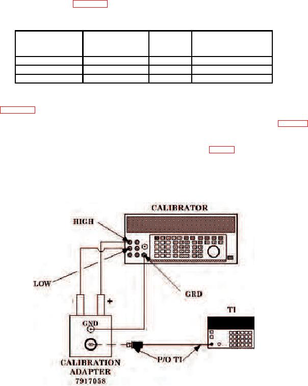
(15) Set calibrator to STBY and disconnect test equipment. Connect equipment as
shown in figure 5.
(16) Repeat (14) above for calibrator outputs and TI pushbuttons listed in table 9.
(17) Disconnect all equipment, press CLEAR pushbutton.
(18) Set control board bit switches to OPERATE MODE (fig. 3).
(19) Set TI LINE power switch to OFF.
(20) Connect sensor to TI interconnect cable.
(21) Set TI LINE power switch to ON and repeat 9 a above.
Figure 5. Dc accuracy - high range - equipment setup.
18