
TB 9-6625-2197-40
Table 3. Power Supply Voltages.
Control box
Voltages
Tolerance
test jack
(V dc)
Min
Max
11
+12
11.75
12.25
12
+5
4.75
5.25
13
-12
-11.5
-12.5
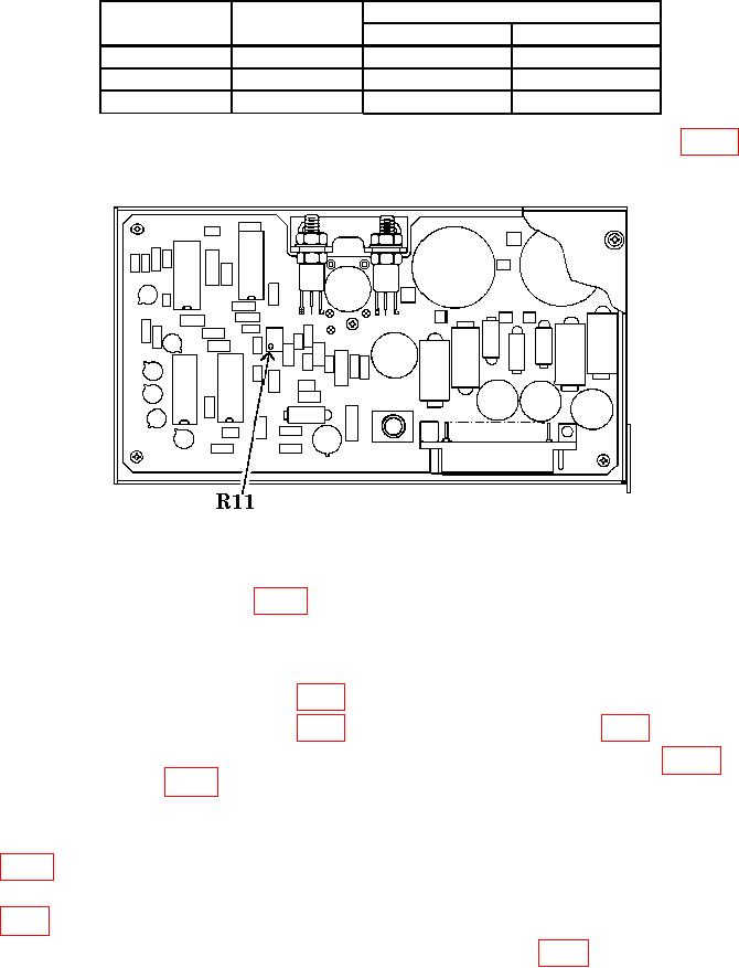
b. Adjustments. Connect multimeter to control box TJ 11 and adjust R11 (fig. 14) for
a multimeter reading between 11.99 and 12.01 V dc.
Figure 14. Power Supply Adjustment Location.
14. Final Procedure
a. Reassemble TI chassis (fig. 4).
(1) Deenergize and disconnect all equipment.
(2) Remove battery stick from TI.
(3) Disconnect CABLE (20) (fig. 4) from attenuator.
(5) Disconnect power supply extender cable from CABLE (8) (fig. 4) and
CONNECTOR (15) (fig. 4).
(6) Disconnect SMA connectors from card cage chassis, SUM and DIFF outputs.
(7) Place upper housing beside card cage chassis and reconnect CABLES (2) and (3)
(8) Install upper housing into card cage chassis while sliding CABLES (2) and (3)
(fig. 4) through seals to take up slack.
(9) Install eight SCREWS and WASHERS (21) and (22) (fig. 4) located on lip of card
cage chassis.