
TB 9-6625-2204-24
(11) Disconnect multimeter and connect oscilloscope to dc load, using appropriate leads.
(12) Adjust DC CONTROL for a 28 V dc indication on TI voltmeter.
(13) Using standard measurement technique, measure the ripple voltage with
oscilloscope. The ripple voltage as indicated by oscilloscope will not exceed 2 V p-p.
(14) Set DC CONTROL fully ccw and set 6 AMP POWER circuit breaker OFF.
Disconnect dc load and oscilloscope from TI.
(15) Set 6 AMP POWER circuit breaker to ON and set TEST CONDITION switch
to VOLTS.
(16) Connect multimeter to MODE C ENCODER J5 pin s and chassis ground, using
appropriate leads.
(17) Adjust DC CONTROL for a 28 V dc indication on TI voltmeter. Multimeter will
indicate between 1 and 2 V dc.
(18) Set all MODE C ENCODER SIMULATOR switches to OFF.
(19) Multimeter will indicate between 18.5 and 21.5 V dc.
(20) Disconnect multimeter from pin s and connect to pins g, b, f, m, p, J, L, P, T, and
F respectively. Multimeter will indicate as specified in (19) above for each pin.
(21) Set DC CONTROL fully ccw and 6 AMP POWER circuit breaker OFF.
b. Adjustments. No adjustments can be made.
9. Pulse Characteristics
a. Performance Check
(1) Connect equipment as shown in figure 3.
(2) Set pulse generator controls for a positive (+) pulse output at a 1 kHz rate.
(3) Adjust pulse generator controls for a 0.5 s pulse 10 V in amplitude as indicated
on oscilloscope CH 2.
(4) Set 6 AMP POWER circuit breaker to ON and adjust DC CONTROL for a
28 V dc indication on TI voltmeter.
(5) Using standard measurement techniques, measure the pulse characteristics
listed in table 4 for the REPLY pulse on CH 1 of oscilloscope. Indications as observed on
oscilloscope will be as specified in table 4.
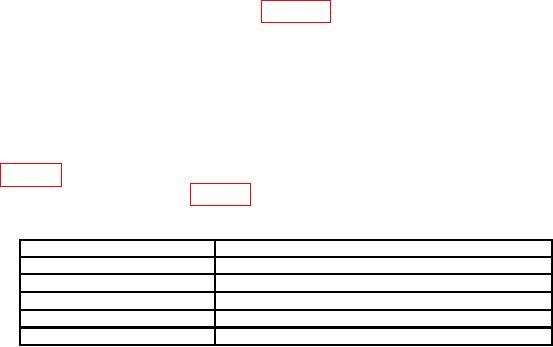
Table 4. Reply Pulse Characteristics
Pulse characteristics
Indication as observed on oscilloscope
Amplitude
4.5 to 5.5 V
0. 45 to 0. 55 s
Width
0.1 s
Rise time
0.25 s
Delay
Negative overshoot
1.5 V