
TB 9-6625-2210-35
(4) Use type 310 phone plug and cable to connect XMT 2W/4W connector to
(5) Type DSPCAL, press RETURN key, and follow instructions as printed on TI
screen.
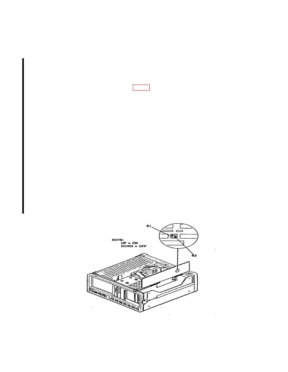
NOTE
EEPROM is write enabled by changing the settings of switch 1
following manner:
1.
Set S2 (nearest rear) to ON (up).
2.
Set S1 (nearest front) to OFF (down).
WARNING
Never allow both S1 and S2 to be OFF (down) at the same
time. Having both OFF will damage DSP board.
(6) The test set will display the following:
"Writing calibration data to EEPROM. Calibration sequences completed.
Please write protect EEPROM. Dump calibration data? (y/n):"
NOTE
When instructed to write protect, do so by first setting S1 to
ON (up), and then setting S2 to OFF (down). See WARNING
above.
(7) Type the following: N
The test set will display the following: A:\>
6 CHANGE 1
