
TB 9-6625-2221-24
(4) Repeat technique of (3) above for frequencies listed in table 4.
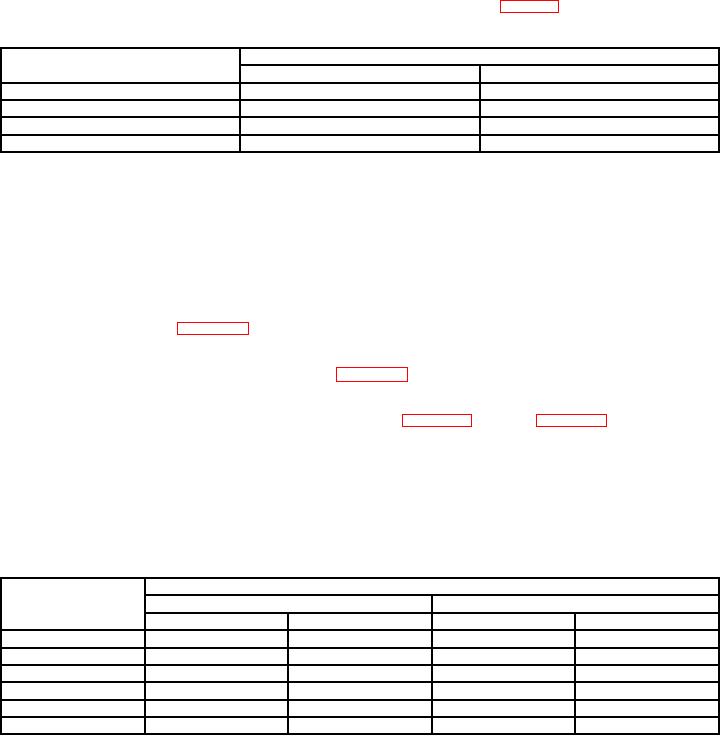
Table 4. Transmitter Frequencies
Frequency counter indications
Test instrument frequency
Min
Max
200
Hz
199.98
Hz
200.02
Hz
1004
Hz
1003.9
Hz
1004.1
Hz
15
kHz
14.9985
kHz
15.0015
kHz
110
kHz
109.989
kHz
110.011
kHz
b. Adjustments. No adjustments can be made.
10. Transmitter Level and Flatness
a. Performance Check
(1) Connect TI TRMT terminals to TI RCVR terminals.
(2) Press hardkey LEVEL; press DATA ENTRY key for level, and press ENTER
key for levels listed in table 5A.
(3) Press hardkey FREQUENCY; press DATA ENTRY key for frequency, and
press ENTER key for frequencies listed in table 5A. TI will indicate within listed values.
(4) Repeat (2) and (3) above with matched TRMT IMP and RCVR IMP impedances
NOTE
To change TRMT IMP and RCVR IMP, press hardkey SET UP
and softkey TRMT/RCVR. Then press softkeys TRMT IMP and
RCVR IMP for equal impedances.
Table 5A. Transmitter Level and Flatness
Level (dB)
Frequency
+13
+10
Min
Max
Min
Max
Hz1
20
+12.5
+13.5
---
---
200
Hz
+12.8
+13.2
---
---
1004
Hz
---
---
+9.8
+10.2
14
kHz
+12.8
+13.2
---
---
84
kHz
+12.5
+13.5
---
---
110
kHz
+12.0
+14.0
---
---
1135:
is not specified above + 5 dB nor below 200 Hz.