
TB 9-6625-2227-35
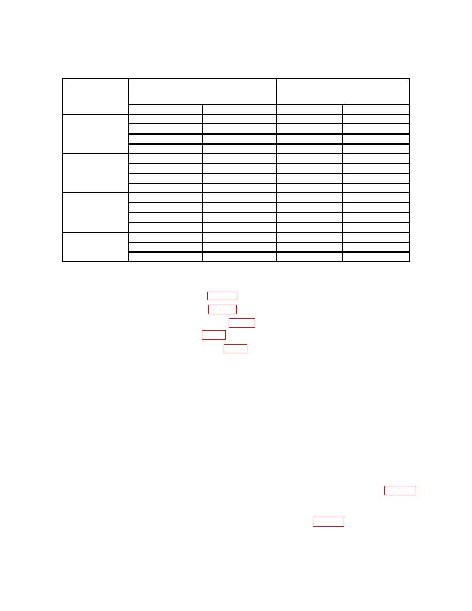
Table 5. Ac Voltage
Test instrument
RANGE
pushbutton
Calibrator output
Test instrument indications
settings
Voltage
Min
Max
200 mV
30
Hz
190
mV
186.9
mV
193.1
mV
100
Hz
190
mV
189.1
mV
190.9
mV
10
kHz
190
mV
189.1
mV
190.9
mV
100
kHz
190
mV
186.1
mV
193.9
mV
2V
30
Hz
1.9
V
1.869 V
1.931 V
100
Hz
1.9
V
1.891 V
1.909 V
10
kHz
1.9
V
1.891 V
1.909 V
100
kHz
1.9
V
1.861 V
1.939 V
200
V
30
Hz
190
V
186.9
V
193.1
V
100
Hz
190
V
189.1
V
190.9
V
10
kHz
190
V
189.1
V
190.9
V
100
kHz
190
V
186.1
V
193.9
V
1200 V
40
Hz
1000
V
982
V
1018
V
100
Hz
1000
V
994
V
1006
V
10
kHz
1000
V
994
V
1006
V
b. Adjustments
(1) Adjust AC ZERO ADJ R203 (fig. 1) for a TI indication of 0.00 V ac (R).
(2) Adjust AC GAIN ADJ R123 (fig. 1) for a TI indication of 19.00 V ac (R).
(3) Adjust 20 V HI FREQ ADJ R102 (fig. 1) for a TI indication of 19.00 V ac (R).
(4) Adjust 20 VAC ADJ C109 (fig. 1) for a TI indication of 19.00 V ac (R).
(5) Adjust 2 V HI FREQ ADJ R110 (fig. 1) for a TI indication of 1.900 V ac (R).
11. Resistance
a. Performance Check
(1) Press FUNCTION kΩ and 20Ω RANGE pushbuttons.
(2) Short VΩ and COM jacks. If TI does not indicate 0.00Ω , perform b(1) below,
then remove short.
(3) Connect calibrator output terminals to TI INPUT VΩ and COM terminals.
(4) Press 2 0 kΩ RANGE pushbutton and set calibrator to nominal 19 kΩ. Adjust the
calibrator output adjustment control knob for a calibrator control display reading equal to the TI
indication. The calibrator control display ERROR indication will be within .3000%; if not, perform
b(2) below.
(5) Set TI range and calibrator to the nominal resistance outputs listed in table 6.
At each resistance input, adjust the calibrator output adjustment control knob for a
calibrator control display reading equal to the TI indication. The calibrator control
display ERROR indication will be within the specified limits of table 6.
