
TB 9-6625-2239-24
10. Delay Time/Differential Time Measurement
a. Performance Check
(1) Position controls as listed in (a) through (e) below:
A TIME/DIV switch to 10 s.
(a)
B TIME/DIV switch to .1 s.
(b)
HORIZ DISPLAY B DLY'D pushbutton to on (in).
(c)
DELAY TIME POSITION dial to 1.00.
(d)
A TRIGGER TRIG MODE AUTO pushbutton to on (in).
(e)
(2) Set oscilloscope calibrator MARKER output to 10 s.
(3) Adjust horizontal POSITION control to align start of sweep with center vertical
graticule line. If leading edge of displayed time marker is not aligned with center vertical
graticule line, perform b (1) below.
(4) Adjust DELAY TIME POSITION dial to 9.00. Slightly readjust the DELAY
TIME POSITION dial to position the leading edge of displayed time marker to the center
graticule line. Check to see that the DELAY TIME POSITION dial setting is between 8.92
and 9.08. If the leading edge of displayed time marker will not align with center vertical
graticule line, perform b (2) below.
(5) Adjust DELAY TIME POSITION dial to 1.00.
(6) Adjust DELAY TIME POSITION dial to position 10th time marker to start of
sweep. Record dial reading.
(7) Adjust DELAY TIME POSITION dial to position 9th time marker to start of
sweep. Record dial reading. Difference in recorded readings will be 0.99 to 1.01.
(8) Repeat technique of (6) and (7) above for each successive time marker.
Difference in recorded readings between adjacent time markers will be within 0.99 to 1.01.
b. Adjustments
(1) Perform appropriate adjustment for TI model number identified in table 8 to
align displayed time marker with center vertical graticule line.
(2) Perform appropriate adjustment for TI model number identified in table 8 to
align displayed time marker with center vertical graticule line.
NOTE
Interaction occurs between adjustments.
Adjust for best
in-tolerance (1%) compromise.
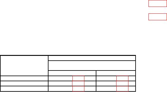
Table 8. Delay/Differential Adjustments
Adjustments (R)
DELAY TIME
dial settings
Model
1.00
9.00
AN/USM-425(V)1
R2782 (fig. 5)
R2748 (fig. 5)
Tektronix, Type 465
R1115 (fig. 6)
R1145 (fig. 6)
Tektronix, Type 465B
R4570 (fig. 7)
R6053 (fig. 3)