
TB 9-6625-2265-24
9. Ac Voltage
a. Performance Check
and COM
(1) Ensure calibrator OUTPUT terminals are connected to TI V-
terminals and set TI FUNCTION/RANGE dial to ACV 2.
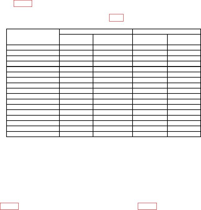
(2) Set TI FUNCTION/RANGE dial and calibrator for voltages and frequencies
listed in table 4. TI will indicate within the specified limits; if not, perform b below.
b. Adjustments. Set TI FUNCTION/RANGE dial to ACV 200m and calibrator for a
190 mV, 400 Hz output. Adjust VR2 AC 200 mV (fig. 1) for a TI indication of 190.0 mV (R).
Table 4. Ac Voltage
Test instrument
Calibrator output
Test instrument indications
FUNCTION/RANGE dial
(ACV)
Voltage
Min
Max
200 M
190
mV
40
Hz
188.4
191.6
200 M
190
mV
1.0 kHz
188.4
191.6
200 M
190
mV
2.0 kHz
186.8
193.2
200 M
190
mV
5.0 kHz
180.0
199.9
2
1.9 V
40
Hz
1.884
1.916
2
1.9 V
1.0 kHz
1.884
1.916
2
1.9 V
2.0 kHz
1.868
1.932
2
1.9 V
5.0 kHz
1.800
1.999
20
19
V
40
Hz
18.84
19.16
20
19
V
1.0 kHz
18.84
19.16
20
19
V
2.0 kHz
18.68
19.32
20
19
V
5.0 kHz
18.00
19.99
200
190
V
40
Hz
188.4
191.6
200
190
V
1.0 kHz
188.4
191.6
200
190
V
2.0 kHz
186.8
193.2
750
750
V
50
Hz
740
760
750
750
V
1.0 kHz
740
760
10. Dc Current
a. Performance Check
(1) Connect calibrator OUTPUT terminals to TI A and COM terminals.
(2) Set TI FUNCTION/RANGE dial to DCA 200 .
(3) Set calibrator OUTPUT for 190 A. Digital multimeter will indicate between
188.5 and 191.5.
(4) Repeat technique of steps (2) and (3) above using settings and indications listed