
TB 9-6625-2271-40
b. Replace top cover and connect TI to a 115 V ac source.
c. Set LINE switch to ON and allow 1 hour for warm-up.
d. Connect calibrator OUTPUT HI and LO to TI INPUT HIGH and LOW using
balanced cable supplied with TI.
NOTE
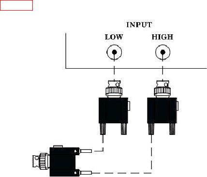
If balanced cable is not available then connect as shown in
figure 2 for this and all future reference to balanced cable.
Figure 2. Input connection.
e. Set calibrator for a 3 V, 1 kHz output.
f. Press LCL INIT key. Press INPUT FLOAT key and verify INPUT FLOAT
indicator is illuminated.
g. Press SPCL key and enter 20 ENTER using DATA ENTRY keys. Allow sufficient
time for ac self-calibration to complete before continuing.
NOTE
As self-calibration is being performed, verify no error codes are
displayed on TI.
h. Disconnect calibrator from TI.
i. Connect TI INPUT LOW to INPUT HIGH using a short cable.
j. Press SPCL key and enter 23 ENTER using DATA ENTRY keys. Allow sufficient
time for dc zero calibration to complete before continuing.
6