
TB 9-6625-2276-24
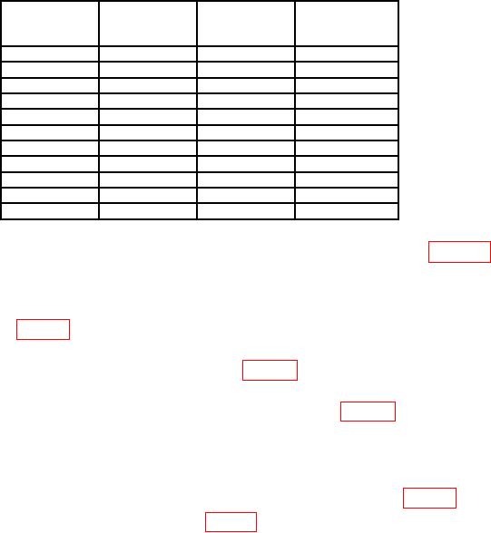
Table 4. Power Amp Gain
POWER AMP
Test frequency
gain
settings
Reference
Raw gain
(dBm)
(MHz)
(dBm)
(dBm)
0.10
1.0
5.0
10.0
100.0
300.0
500.0
700.0
900.0
1100.0
1300.0
with the following exceptions: Move PRE-AMP IN connection to POWER AMP IN and
move PRE-AMP OUT connection to POWER AMP OUT.
(26) Turn signal generator RF output on and record measuring receiver indication in
raw gain column in table 4.
(27) Turn signal generator RF output off and repeat technique of (23) through (26)
above for remaining test frequency settings listed in table 4.
(28) Algebraically subtract raw gain recorded for 0.10 MHz test frequency setting
from -40 dBm. Record difference in POWER AMP gain column of table 4.
NOTE
Disregard sign of difference determined in (29) above.
(29) Repeat (29) above for remaining test frequency settings listed in table 4.
(30) POWER AMP gain values recorded in table 4 will be between 20.5 and 23.5 dBm.
(31) Disconnect TI from equipment setup.
b. Adjustments. No adjustments can be made.
9. Distortion Check
a. Performance Check
(1) Connect sensor module to the power reference output. Perform sensor zero and
(2) Configure measuring receiver to measure power.
to PRE-AMP IN.
(3) Connect signal generator INPUT 50
(4) Connect PRE-AMP OUT to measuring receiver power sensor.
NOTE
Use cable for (4) above.