
TB 9-6625-2284-40
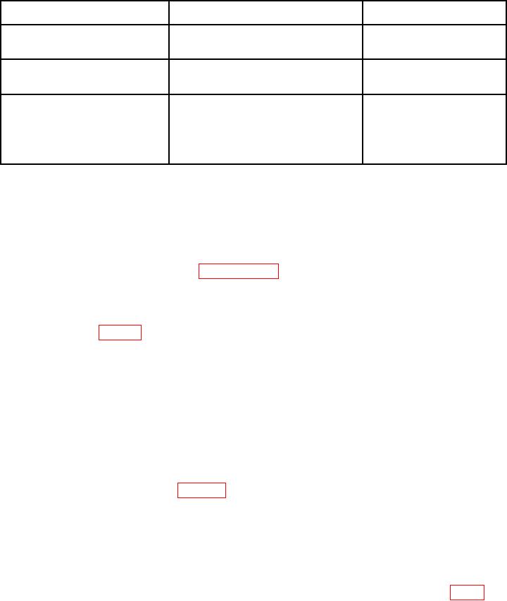
Table 2. Minimum Specifications of Equipment Required
Manufacturer and model
Common name
Minimum use specifications
(part number)
Intensity at 810 (nominal): 3.03 x 10 -8
AUXILIARY SOURCE
Test set electronic systems
(REFERENCE)
W/sr
(modified TS-4348/UV)
(TS-4348/UV modified)
Range: 100 to 800 mV
Agilent, Model 3458A (3458A)
V dc resolution: .01mV
Accuracy: 0.5% at 500 mV
Radiance responsitivity at 820 nm:
PN 13335470 (13335470)
SECONDARY
4.73 x 10⁷(nominal) V/ (W Cm-2sr-1)
REFERENCE NIGHT VISION
(Selected, Blue Anodized with
DEVICE
2.5% (6%)
Calibration Test Report)
DETECTOR STANDARD
Intensity responsitivity at 810 nm:
1.51 x 10⁷ V/ (W sr-1) 2.8% ( 7.5%)
Procedure end item (TI) tolerance restricted to 8% to maintain end item overall uncertainty of 10%, 11% respectively
1
CALIBRATION PROCESS
6. Preliminary Instructions
a. The instructions outlined in paragraphs 6 and 7 are preparatory to the calibration
process. Personnel should become familiar with the entire bulletin before beginning the
calibration
b. Items of equipment used in this procedure are referenced within the text by common
name as listed in table 2.
c. Unless otherwise specified, verify the result of each test and, whenever the test
requirement is not met, take corrective action before continuing with the calibration.
Adjustments required to calibrate the TI are included in this procedure. Additional
maintenance information is contained in the manufacturer's manual for this TI.
d. Unless otherwise specified, all controls and control settings refer to the TI.
7. Equipment Setup
a. Momentarily energize both secondary reference and transfer NVD detector
standards; press battery test pushbutton and verify that red LED illuminates; if not,
replace batteries and retest (see figure 1).
b. Remove auxiliary source (TS-4348/UV) from its protective case and orient vertically.
c. Install NVD alignment collar on the auxiliary source collimator port, ensuring that
its scribe line is aligned with that on the body of the auxiliary source.
d. Firmly seat secondary reference NVD detector standard (blue anodized) into the
NVD alignment collar, rotating in a clockwise direction until the scribe lines on the
reference detector standard are in alignment with the auxiliary source scribe lines (fig. 2).