
TB 9-6625-2295-35
Test instrument
Test instrument
CAL 01
Oscilloscope
superimposed
displayed
calibrator
displayed B
∆REF
∆
step number
output settings
sweep division
time marker
time marker
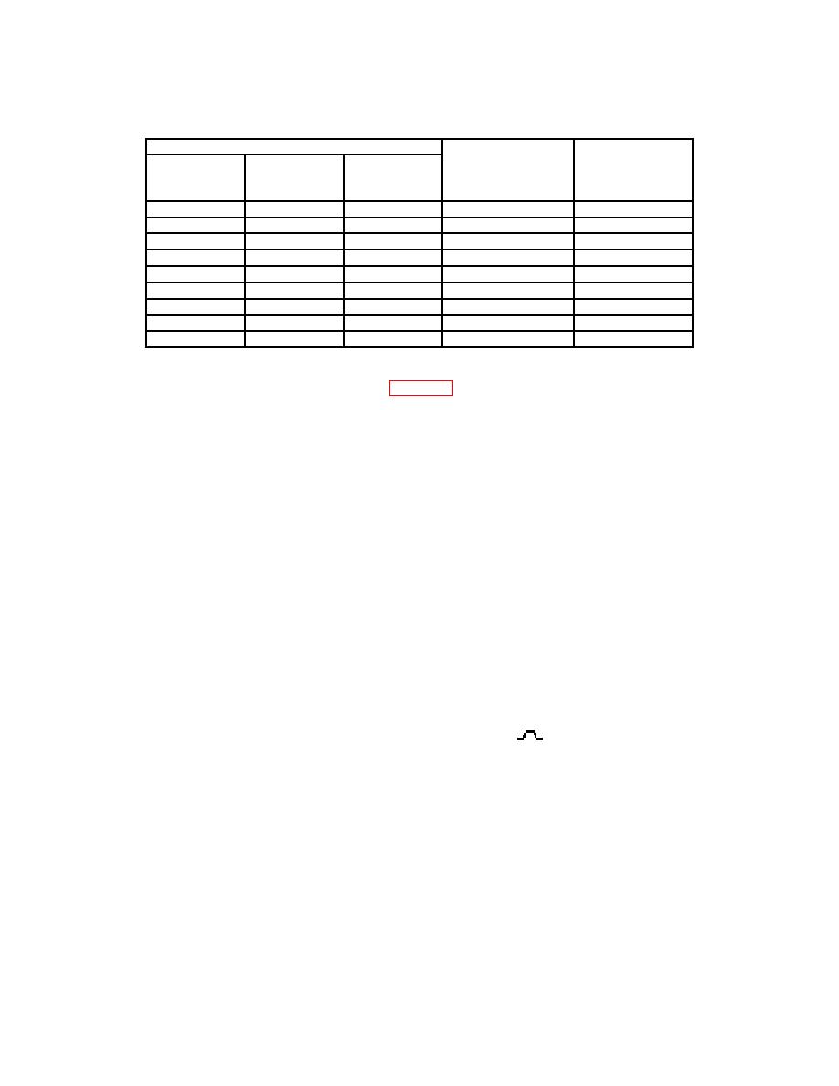
7
2
10
0.2
1 s
8
2
10
0.2
2 s
91
4
28
1.2
2 s
10
2
10
0.2
10 s
11
2
10
0.2
50 s
121
4
28
1.2
50 s
13
2
10
0.2
.5 s
141
4
28
1.2
.5 s
15
3
19
50 ns
0.2
If ∆ control is adjusted; the previous step will be repeated.
1
(32) After completion of step 15 of table 23, TI display will indicate ADJ ∆, (step) 16,
20 ns, 500 ps.
(33) Set oscilloscope calibrator for a CHAN 1, MARKER mode output of 20 ns.
(34) Adjust ∆ control for approximately 1 time marker per division. Set oscilloscope
calibrator for a CHAN 1, MARKER mode output of 2 ns.
(35) Set VOLTS/DIV switch for a display amplitude of >3 division. Adjust ∆ control
to superimpose displayed B sweep time markers.
(36) Press and release upper TRIGGER COUPLING pushbutton and display
readout will indicate ADJ ∆, (step) 17, 1 s.
(37) Return VOLTS/DIV switch to original setting.
(38) Adjust TRACE SEP control fully cw.
(39) Connect oscilloscope calibrator SOURCE/MEASURE CHAN 1 to TI CH 1 and
oscilloscope Vertical 1 input.
(40) Connect TI B GATE OUT to oscilloscope Vertical 2 input.
(41) Set oscilloscope controls as listed in (a) through (c) below.
(a) Vertical 1 and 2 Coupling to DC, Input to 50 Ω, and Vertical 1 on.
(positive).
(b) Trigger Source to 2 and Trigger Slope to
(c) Sweep speed to 20 ns.
(42) Set oscilloscope calibrator for a CHAN 1, MARKER mode output of 1 s.
(43) Adjust TI ∆ control for 8 time markers over center 8 major divisions of TI
display. Adjust TI ∆ REF OR DLY POS control to bring time markers onto oscilloscope
display.
31
