
TB 9-6625-2296-24
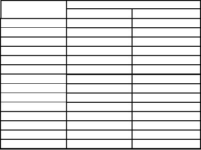
Table 11. Vertical Deflection Accuracy.
Test instrument
Calibrator indications
Scale settings
Min
Max
4.1006
mV
2
mV
2.9694
mV
9.5445
mV
5
mV
8.1305
mV
19.089
mV
10
mV
16.261
mV
38.178
mV
20
mV
32.522
mV
95.445
mV
50
mV
81.305
mV
190.89
mV
100
mV
162.61
mV
381.78
mV
200
mV
325.22
mV
954.45
mV
500
mV
813.05
mV
1.9089
V
1
V
1.6261
V
3.8178
V
2
V
3.2522
V
9.5445
V
5
V
8.1305
V
19.089
V
10
V
16.261
V
38.178
V
20
V
32.522
V
95.445
V
50
V
81.305
V
(5) Connect oscilloscope calibrator to TI SCOPE IN using 50 Ω feedthrough
termination.
(6) Press Sweep (F3) key, adjust DATA SCROLL knob to select 20 s, and press
DATA ENTRY ENTER key.
(7) Press Scale (F1) key, adjust DATA SCROLL knob to select 10 mV, and press
DATA ENTRY ENTER key.
NOTE
If necessary, press Vert (F2) key and use DATA SCROLL
controls to position waveform vertically on display.
(8) Set oscilloscope calibrator level sine output for 50 kHz and 6 divisions of vertical
deflection on TI.
(9) Set oscilloscope calibrator leveled sine wave frequency to 1 MHz. Press Sweep
(F3) key and use DATA SCROLL controls, as necessary, to view waveform. Displayed
waveform will be greater than 4.2 divisions.
(10) Repeat technique of (6) through (9) above for Scale 100 mV.
NOTE
For (11) through (15) below; press Scale (F1) key, use DATA
SCROLL controls to set convenient display amplitude, press
Vert (F2) key, and use DATA SCROLL controls to position
markers vertically on display as necessary.
(11) Press Sweep (F3) key, adjust DATA SCROLL knob to select 1 s, and press
DATA ENTRY ENTER key.
(12) Set oscilloscope calibrator markers output for 1 s.
36