TB 9-6625-2310-35
(6) The difference between the high and low indications will be between 0.96334
and 1.00266 V dc.
(7) Repeat technique of (4) through (6) above for remaining ACC SIGNAL
within the limits specified.
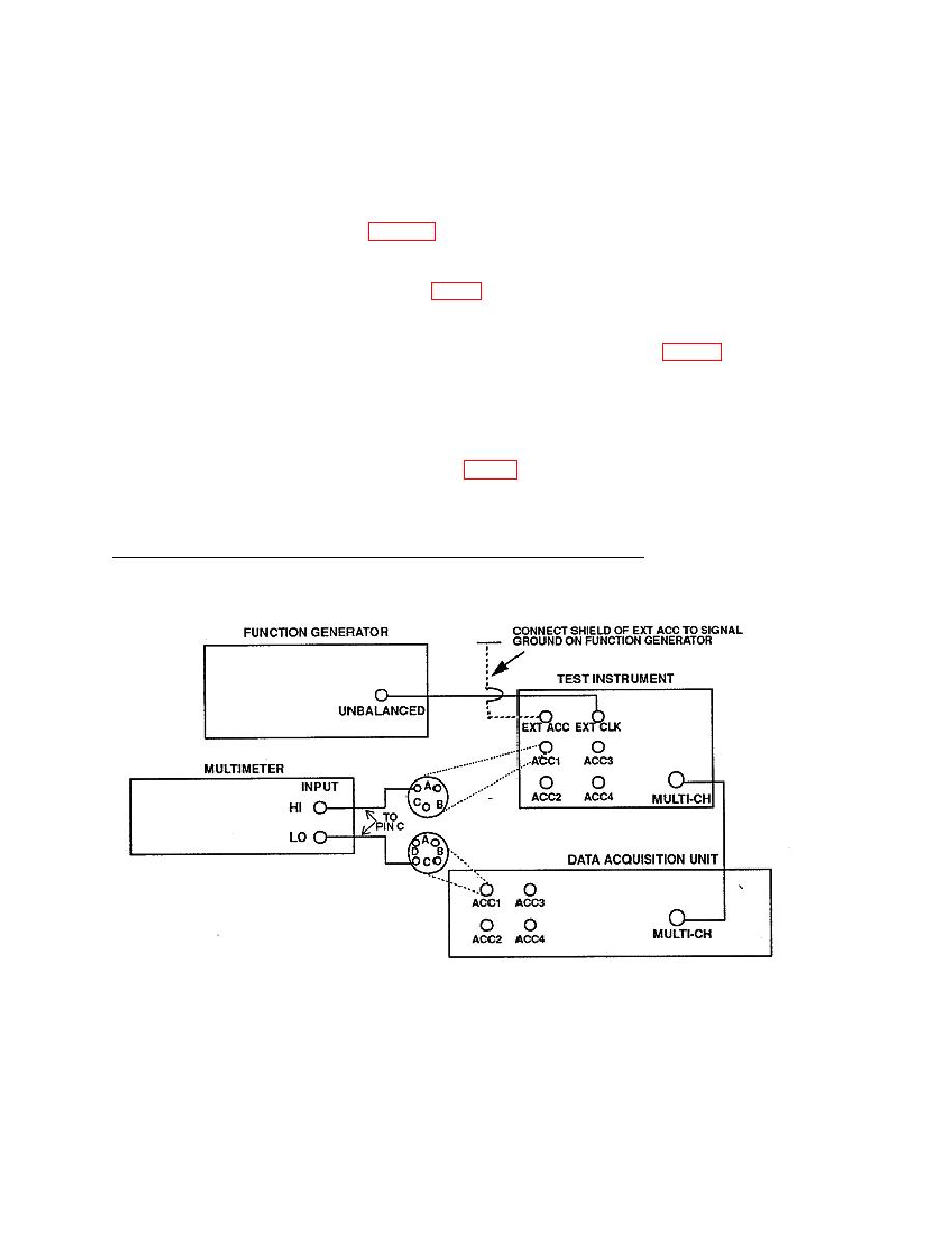
(8) Move multimeter connections (fig. 2) from pins C of ACC 1, both TI and DAU, to
pins C of ACC 2.
(9) Repeat technique of (4) through (7) above, recording results in table 3, ACC 2 row.
(10) Repeat technique of (8) and (9) above for ACC 3 and ACC 4.
(11) Set ACC 1 through ACC 4 channel switches to 54 mV/g.
(12) Connect equipment as shown in fig. 2, except connect multimeter to pin B on
both ACC1 connectors.
(13) Repeat technique of (4) through (11) above for 54 mV/g channel switch position;
however, connect multimeter to pins B while taking measurements.
b. Adjustments. No adjustments can be made.
6


