
TB 9-6625-2328-24
5. Accessories Required. The accessories required for this calibration are common
usage accessories, issued as indicated in paragraph 4 above, and are not listed in this
calibration procedure.
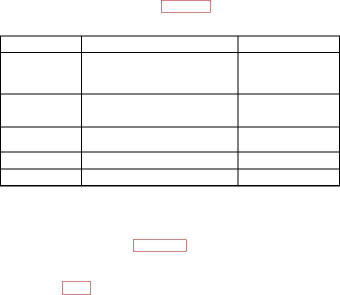
Table 2. Minimum Specifications of Equipment Required.
Minimum use
Manufacturer and model
Common name
specifications
(part number)
CALIBRATOR
Range:
-2 to 5 V dc
Fluke, Model 5720A (5700A)
(p/o MIS-35947); w/ amplifier,
Accuracy:
0.75%
Fluke 5725A/AR (5725A/AR)
Frequency: 1 MHz
Range:
0.707 V ac
Accuracy:
3%
Agilent, Model 33250A
FUNCTION
Function:
Square wave
GENERATOR
Frequency: 1 and 10 MHz
(33250A)
Output level: 80 mV p-p and 1 V p-p
DC offset:
-60 to +60 mV
PULSE GENERATOR
Pulse width: 150 ns
Agilent, Model 81150A Pulse
Function Arbitrary Noise
Accuracy:
0.67%
Generator (81150A)
SIGNAL
Frequency: 1 to 1300 MHz
Aeroflex, Model 2023B
GENERATOR
Output level: -60 to 7 dBm
(2023B) or (SG-1207/U)
TIME/FREQUENCY
Range:
1 and 10 MHz
Datum, Model ET6000-75
10
WORKSTATION
(13589305)
Accuracy:
1.25 parts in 10
CALIBRATION PROCESS
6. Preliminary Instructions
a. The instructions outlined in paragraphs 6 and 7 are preparatory to the calibration
process. Personnel should become familiar with the entire bulletin before beginning the
calibration.
b. Items of equipment used in this procedure are referenced within the text by common
name as listed in table 2.
c. Unless otherwise specified, verify the result of each test and, whenever the test
requirement is not met, take corrective action before continuing with the calibration.
Additional maintenance information is contained in TM 9-6625-907-40.
d. Unless otherwise specified, all controls and control settings refer to the TI.
7. Equipment Setup
WARNING
HIGH VOLTAGE is used or exposed during the performance of
this calibration.
DEATH ON CONTACT may result if
personnel fail to observe safety precautions.
REDUCE
OUTPUT(S) to minimum after each step within the
performance check where applicable.
a. Connect TI to a 115 V ac power source.