
TB 9-6625-2334-24
(5) Set calibrator output for settings listed in table 12. If TI does not indicate within
limits specified, perform corresponding adjustments.
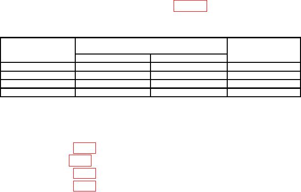
Table 12. Digital Voltmeter Check
Calibrator output
Test instrument
settings
indications (V)
(V dc)
Min
Max
Adjustments
b(2)
+9.5
+9.5033
+9.4967
b(3)
-9.5
-9.5033
-9.4967
b(4)
+95
+94.967
+95.033
b(5)
+950
+949.13
+950.87
b. Adjustments
(1) Adjust DVM zero A6R28 (accessible through a hole in TI front panel located
above the READ A pushbutton) for a TI indication between -0.0001 and +0.0001 (R).
(2) Adjust A7R13 (fig. 1) for a TI indication between +9.4999 and +9.5001 (R).
(3) Adjust A7R6 (fig. 1) for a TI indication between -9.4999 and -9.5001 (R).
(4) Adjust A6R29 (fig. 1) for a TI indication between +94.999 and +95.001 (R).
(5) Adjust A6R15 (fig. 1) for a TI indication between +949.99 and +950.01 (R).
13. Final Procedure
a. Deenergize and disconnect all equipment and reinstall TI protective cover.
b. Annotate and affix DA label/form in accordance with TB 750-25.