
TB 9-6625-2337-35
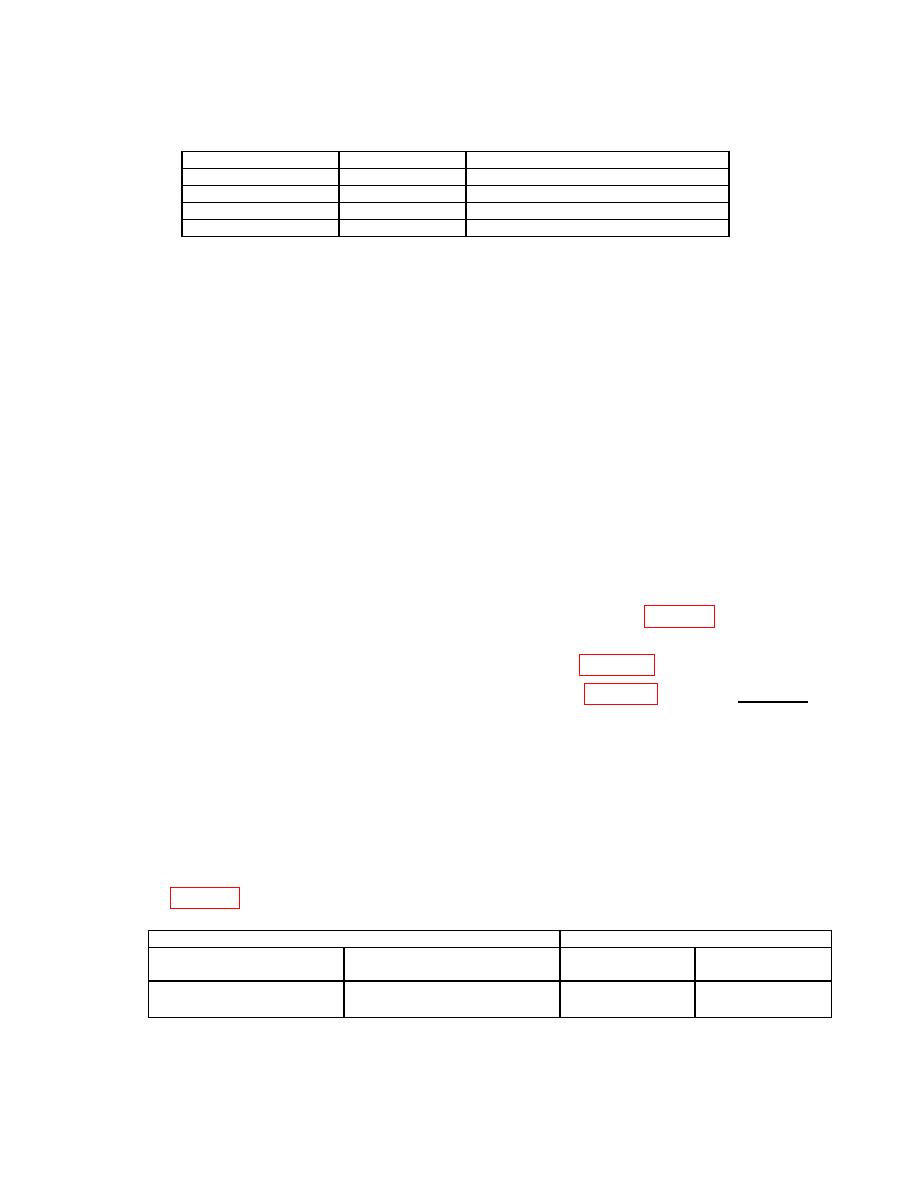
Standard
Reading
Directional coupler
1030 MHz
Directional coupler
1090 MHz
20 dB attenuator
1090 MHz
20 dB attenuator
1030 MHz
(2) Press TI keys as listed in (a) through (e) below:
(a)
Press FUNC, ENTR keys.
(b)
Use the arrow keys to highlight GENERAL MENUS and press ENTR key.
(c)
16, ENTR (GENERAL MEASUREMENTS).
(d)
Use the arrow keys to highlight TYPE:.
(e)
ENTR (CW).
(3) Connect the power amplifier to +13 V output of dc power supply, monitored
with multimeter.
(4) Connect the signal generator to the power amplifier input.
(5) Connect power amplifier output to directional coupler.
(6) Connect the main output of the directional coupler to the TI MAIN RF I/O 1W
TO 10 KW input connector.
(7) Connect the 20 dB sample output of the directional coupler and a 20 dB
attenuator to the measuring receiver.
(8) Compute the measuring receiver indication by algebraically adding the
attenuator value and directional coupler coupling value recorded in table 41 above, then
subtracting the total from +40 dBm.
EXAMPLE:
Directional Coupler value recorded in table 41 above = 19.90 dB
Attenuation value recorded in table 41 above =
19.81 dB
39.71 dB
Measuring receiver indication: 40 dB 39.71 dB = 0.29 dB
receiver indication equal to the value calculated in (8) above.
(10) Use the arrow keys to highlight POWER and press ENTR key.
(11) Verify the TI measured value displayed on the monitor is +40.0 dBm 0.5 dB.
(12) Repeat technique of (4) through (11) above for remaining settings and limits
listed in table 42.
TI
TI CW indication
Test description
Settings
Minimum
Maximum
(dB)
(dB)
1090 MHz 10W (40 dBm)
----------------------------------------
39.5
40.5
MAIN I/O
66
