
TB 9-6625-2339-35
(15) Convert the marker amplitude reading (Mkr1) from volts to dBm using the
equation in step (12) above and record value in table 16.
(16) Subtract the measuring receiver reading recorded in step (5) above from the
marker amptd calculated in step (15) above and record in table 16 as absolute amplitude
accuracy (Lin). Verify the difference recorded in table 16 is between the limits specified.
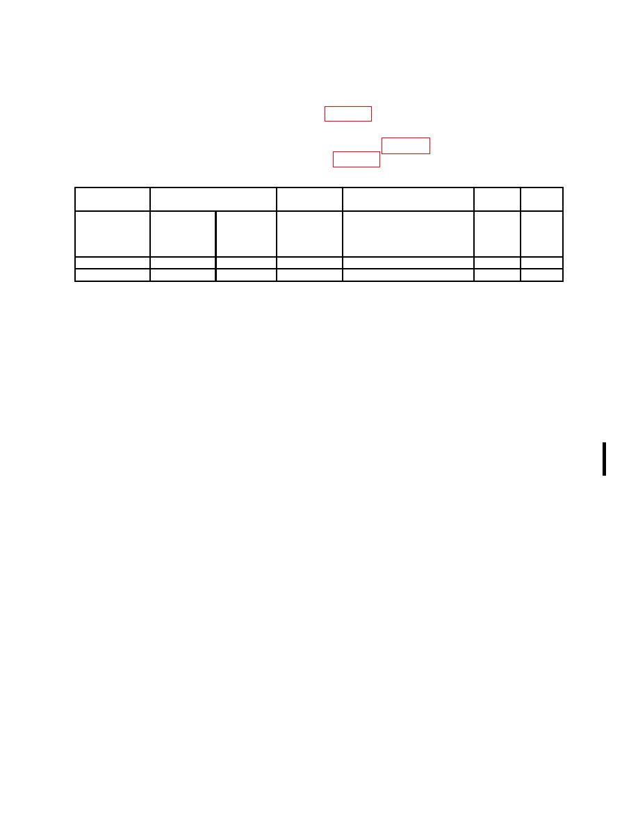
Measuring
Test instrument
Absolute Amplitude
Receiver
Accuracy
Mkr1
Scale
Min
Max
Accuracy = converted
Converted
Actual power
type
amplitude
marker amplitude (dB)
marker
(dB)
(volts)
(dB)
(dB)
measuring receiver reading
amplitude
(dB)
(dB)
Log
-0.34
0.34
Lin
-0.34
0.34
(17) Press TI keys and enter values as listed in (a) though (d) below:
(a) Preset. Press the Factory Preset softkey if it is displayed.
(b) System.
(c) [Alignments].
(d) [Auto Align], [All].
(18) Set all outputs to minimum and disconnect equipment setup.
b. Adjustments. None
16. Resolution Bandwidth Accuracy
a. Performance Check
(1) Connect TI 10 MHz Ref Out to synthesizer/level generator 40/N MHz REF and
synthesizer/level generator OUTPUT 50 Ω to TI RF INPUT 50 Ω.
(2) Press synthesizer/level generator keys to values as listed in (a) and (b) below:
(a) FREQUENCY to 50 MHz.
(b) AMPLITUDE to -5 dBm.
(3) Press TI keys and enter values as listed in (a) through (j) below:
(a) Preset.
(b) Factory Preset softkey if it is displayed.
(c) System, [Alignments], [Auto Align], [Off].
(d) Sweep, [Points 401].
(e) FREQUENCY, 50, [MHz].
(f) SPAN, 7.5, [MHz].
(g) AMPLITUDE, [Scale/Div], 1, [dB].
(h) AMPLITUDE, [Y Axis Units] (or Amptd Units), [dBm].
(i) BW/Avg, 5, [MHz].
(j) BW/Avg, [Video BW], 30, [Hz].
(4) Press TI Peak Search (or Search), [Meas Tools], [Mkr → CF].
