
TB 9-6625-340-35
(4) above (R).
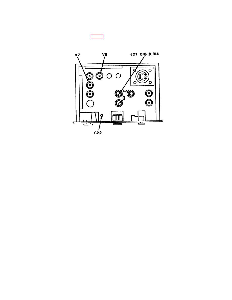
Figure 2. Test instrument - bottom view.
9. Power Input
a. Performance Check
(1) Position controls as listed in (a) through (e) below:
(a) POWER RANGE switch to 3.0 MW +5 dBm.
(b) POWER control to 0 on 0 to 3.0 scale.
(c) BIAS-READ switch to BIAS.
(d) LINE ON switch to ON (up).
(e) COMP ATTENUATOR control to 0 db.
(2) Adjust BIAS COARSE and FINE controls for a null indication on TI NULL
INDICATOR meter.
(3) Set BIAS-READ switch to READ and observe that null indication remains on
TI NULL INDICATOR meter.
(4) Set POWER RANGE switch to 10 MW +10 DBM and BIAS-READ switch to
BIAS.
6
