TM 9-4931-294-15/2
of the selected sweeps may be present on the reference
the rf head. When the sampled voltage increases above
voltage signal. The output of the regulator error amplifier
this reference level, an output from the highvoltage
is applied via emitter follower Q703 to pass transistors
monitor circuit is applied to voltage limit difference
amplifier Q520 in the regulator error amplifier circuit,
Q701 and Q702, and constitutes the control signal which
where it performs a voltage limiting function. Relay K703
determines the amplitude of the drive voltage applied to
applies the collector voltage to resistive load R725R732
the highvoltage circuits.
during CW operation or to constant current load V701
(2) High voltage circuits.
and V702 during sweep operation. Constant current load
V701 and V702 is used to maintain a constant current
(a) The 12kHz oscillator Q704 and Q705
level when the collector voltage is swept during A F,
generates a 12kHz square wave which is applied to the
internal, or external sweep modes of operation. The
bases of chopper transistors Q706 and Q707. The
beta network is part of the regulation feedback loop and
lowvoltage dc output from pass transistors Q701 and
samples the output of the highvoltage circuits. The
Q702 is applied to the center tap of the primary of stepup
output of the beta network is applied through the shaping
transformer T703. The 12kHz oscillator input switches
network in the rf head to the regulator error amplifier.
the chopper transistors alternately on and off. This
(3) Shaper network.
switching action chops the dc voltage applied to the
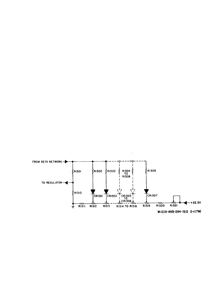
(a) The shaper network is physically located in
center tap of transformer T703 by alternately grounding
the rf head and compensates for the nonlinearity of the
each end of the primary winding. The chopped dc is
BWO tube's helixvoltage vs frequency characteristics.
stepped up by transformer T703 and applied to bridge
As noted previously, to obtain a linear increase in
rectifier CR705CR708 and the highvoltage filter network.
frequency, the helix voltage must have an inverse
The dc output of the filter is applied to the collector of the
exponential rise. The shaper network provides this
BWO tube, the highvoltage monitor circuit, and Zener
inverse exponential feedback voltage by adding an
diodes VR704 and VR705. The total voltage drop across
exponential component to the sampled highvoltage input
the Zener diodes is 130 volts. The output of the Zener
from the beta network.
diodes is applied to the beta network, the armature of
(b) The shaper (figure 2---11) consists of a
relay K703, and through the tunable synchronizer, where
resistive network and diodes CR1801 through CR1308.
a phase locking correction voltage is added, to the helix
A +22.5volt bias is applied to the diodes through series
of the BWO tube.
resistors R1321 through R1311. As a result, the bias
(b) The highvoltage monitor circuit samples the
voltage
high voltage and compares this sample to a reference
level set by highvoltage limit potentiometer R1403 in
Figure 2-11. Shaper Network, Simplified Schematic.
2-13


