
TM 9-4931-294-15/2
+22.5 volts to the regulated anode supply is delayed until
feedback reference voltage.
c. Low Voltage Power Supply. The low voltage
90second thermal time delay relay K701 closes. With
relay K701 closed, 40 volts and +22.5 volts become
supplies consist of the regulated +6.8volt supply, the.
available at contacts of control relay K702. Placing HI
varactor bias supply, the regulated 22.5volt supplies,
VOLT switch S102 to ON energized control relay K702,
and the 40volt supply.
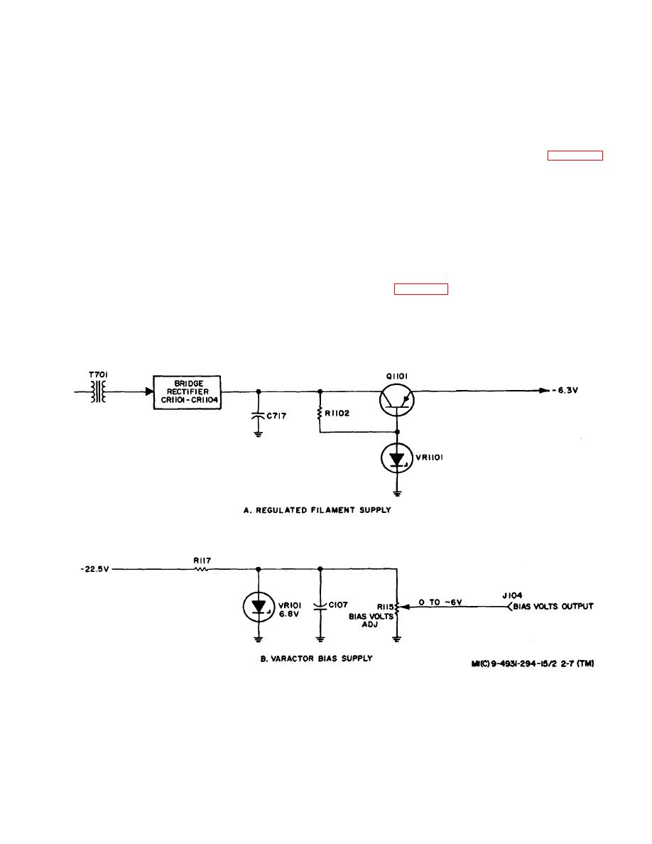
(1) Regulated 6.3Volt DC Filament Supply. The ac
feeding unregulated 40 volts to the helix supply and
regulated +22.5 volts to the anode supply.
input for the filament supply (part A of figure 2-7) is
(2) Closure of HI VOLT switch S102 also applies
applied from one secondary winding of transformer T701
primary power to transformer T704. The secondary
to bridge rectifier CR1101 through CR1104.
The
output of T704 is fed to the regulated anode supply,
rectified voltage is filtered by capacitor C717 and applied
which provides the anode voltage to the rf head. Placing
to pass transistor Ql101. The base voltage of the pass
SQUARE WAVE SELECTOR switch S105 to ON
transistor is held at a constant level by Zener diode
provides squarewave modulation of the anode supply
VR1101, causing the collector to emitter resistance to
output voltage.
increase when the filament voltage increases and to
(3) The de output of the helix supply serves as the
decrease when the filament voltage decreases, thereby
source of both the BWO helix and collector voltages.
regulating the +6.8volt filament supply output.
The magnitude of the helix voltage is controlled by a
feedback reference voltage from FREQUENCYMC
(part B of figure 2-7) is biased through resistor R117 by
control R1502 located in the rf head. When sweep
22.5 volts. The Zener diode
operation is used, a sweep generator associated with the
helix supply adds a sweep voltage component to the
Figure 2-7. Regulated Filament Supply and Varactor Bias Supply, Functional Diagram
2-9
