TM 9-4931-294-15/2
b. BWO Tube.
2-7. Rf Heads
(1) The BWO tube is a voltage tunable oscillator
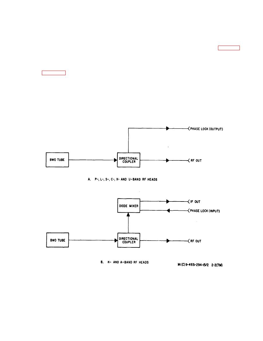
a, General. Seven interchangeable rf heads are
operating over a wide frequency band. The basic
used to cover the eight frequency bands from 500 MHz
structure of a BWO tube is illustrated in figure 2-3. The
to 40 GHz. Six of these rf heads (P, L, S, U, K, and
tube comprises an electron gun, a helix, an electron
Abands) contain components enabling each to cover a
collector, and a terminating resistance. Not shown in the
single band while the Cand Xband components are
illustration is a permanent magnet, surrounding the tube,
physically packaged in one rf head. Each rf head
which serves to confine the electron beam to limits within
contains a BWO tube and associated microwave
the helix. The electron gun consists of a cathode, which
components (figure 2-2) functioning in a particular
emits electrons, and an anode which controls the
frequency band. In order for the BWO power supply to
electron beam. The helix is a form of delay line. Energy
provide the individual voltage requirements of each BWO
propagating down the length of the helix approaches the
tube, portions of its circuitry must change whenever an rf
speed of light in a helical direction but travels at a
head, and thereby a BWO tube, is changed. To
reduced velocity in an axial direction. The axial velocity
accomplish this change, the circuitry of the BWO power
of this energy is determined by the geometry of the helix.
supply thus affected is physically mounted within the rf
head.
In this manner the BWO power supply is
(2) The electron beam emerging from the delay
automatically adjusted to provide the requirements of
line is drawn to the collector electrode at
each
BWO
tube.
Figure 2-2. Rf Heads, Block Diagram.
2-4


