
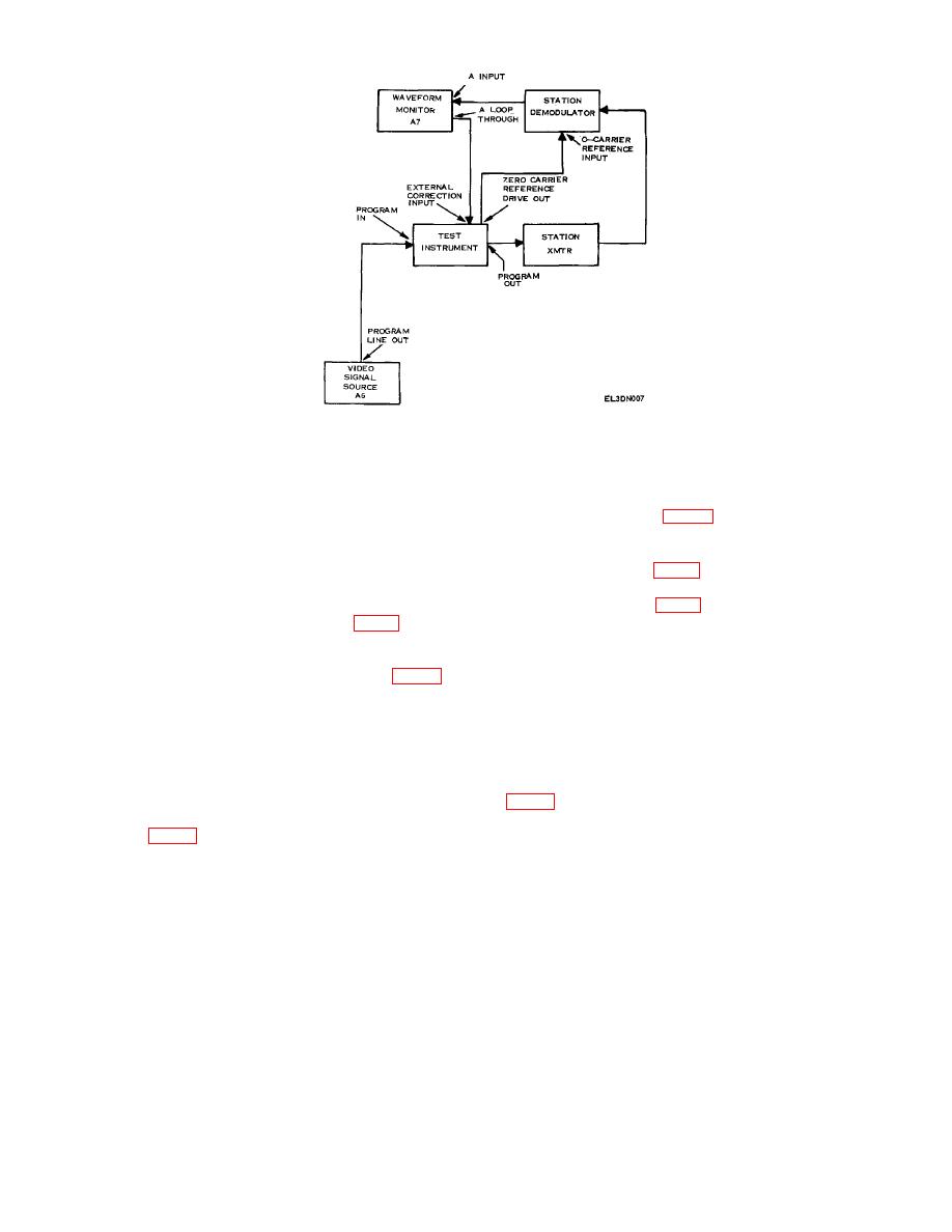
Figure 7. Demodulator control - equipment setup.
b. Adjustments
(3) Set HORIZONTAL DISPLAY control on
waveform monitor (A7) to 2 FIELD and MAGNIFIER to
(1) Adjust R678 (fig. 6) until start of O-carrier
X25.
reference pulse is 12 microseconds from leading edge of
(4) Adjust waveform monitor controls to display 0-
horizontal sync pulse.
carrier reference pulse. If start of 0-carrier reference
(2) Adjust R687 (fig. 6) for 0 volt dc indication on
pulse is not 12 +1 microseconds from leading edge of
oscilloscope.
horizontal sync pulse, perform b(1) below.
(3) Adjust R688 (fig. 6) for 0-volt dc indication on
(5) Adjust gain of station demodulator (fig. 7) for 0-
oscilloscope.
carrier reference pulse amplitude of 120 IRE (857
millivolts).
13. Power Supply.
(6) Connect oscilloscope (A4) to P679-5 (fig. 6),
using probe (B2).
NOTE
(7) If oscilloscope does not indicate approximately 0
Do not perform power supply checks if all
volt, perform b(2) below.
other parameters are within tolerance.
(8) Adjust demodulator gain for 0-carrier reference
pulse amplitude of 100 IRE (7.14 millivolts). Verify that
a. Performance Check
VIR signal 50 IRE level to O-carrier reference pulse ratio
(1) Connect dc voltmeter (A3) to -15 volt test point
is correct.
(9) Connect oscilloscope probe to junction of R5307
indicate between -14.85 and -15.15 volts, perform b(1)
and R5606 (fig. 4). If oscilloscope does not indicate
below.
approximately 0 volt, perform b(3) below.
(2) Adjust output of autotransformer (Al) from 105 to
125 volts ac then back to 115 volts. DC voltmeter
indication will remain between -14.85 and -15.15 volts.
12

