
7. Preliminary Procedures. a. Remove the unit under test
from its case as follows:
(1) Unlatch and remove cover of unit under test.
(2) Remove the sixteen machine screws that secure
panel of unit under test in its case.
(3) Carefully lift panel out of case.
(4) Position panel on a clean work area for
convenient access to both the front and rear of panel.
b. Connect equipment as shown in A, figure 3.
c. Adjust electronic voltmeter for 300 volt operation
and energize voltmeter. Allow 5 minutes for voltmeter
stabilization.
d. Energize 115 vac, 400 Hz primary power circuit
and adjust variable transformer for a 45 volt indication on
electronic voltmeter. Change metering range of
electronic voltmeter as required.
e. Deenergize 115 vac, 400 Hz primary power
circuit and disconnect electronic voltmeter from variable
transformer. Do not disturb setting of transformer control.
f. Connect equipment as shown in B, figure 3. Do
not connect electronic voltmeter to barrier strip at this
time.
NOTE
The following paragraphs are divided
into subparagraphs a, performance
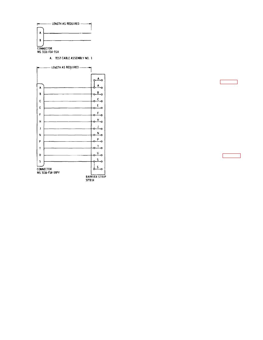
B. TEST CABLE ASSEMBLY NO.2
check and subparagraphs b and c,
adjustments. When the performance
NOTE: ALL CABLE CONDUCTORS ARE
check is not within tolerance and no
STRANDED NO. 18 AWG, INSULATED
adjustment is specified, the deficiency
must be corrected before continuing with
EL 5995-207-35/1-TB-2
the procedure.
Figure 2. Simulator test cable assemblies No. I and No. 2
4

